SOLIDWORKS Sheet Metal Design for Fabrication: A Practical Workflow
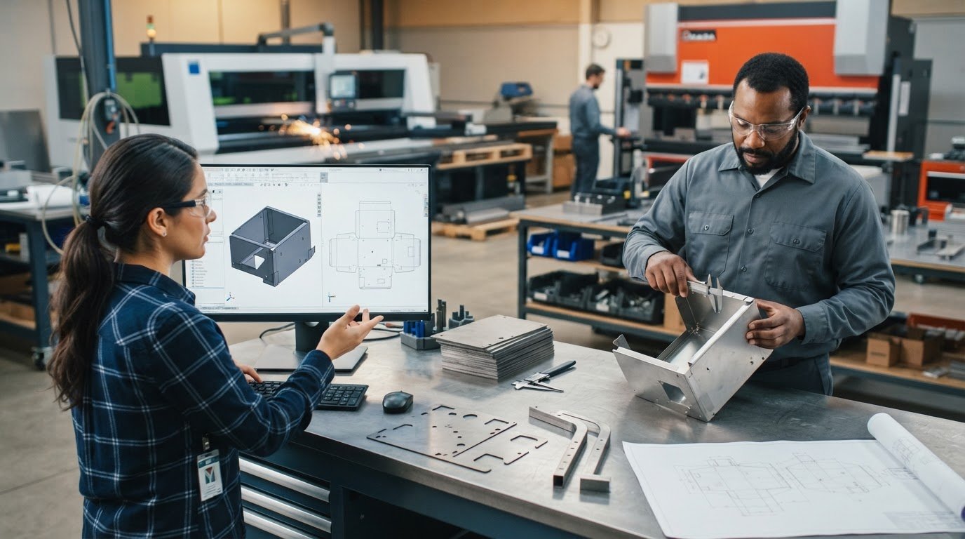
A sheet metal part can look right in SOLIDWORKS and still create problems on the shop floor. The gap often comes down to bend behavior, incomplete flat patterns, or drawings that leave fabrication intent unclear. SOLIDWORKS sheet metal design for fabrication needs to account for the full handoff, not just the finished 3D shape.
If you’ve had to revisit sheet metal settings or clarify a drawing after release, you know the challenge: a model is useful only when its fabrication outputs make sense, too. This guide covers a practical workflow for building a coherent model, checking the flat pattern and drawing, and preparing clear information for fabrication. You’ll see how feature sequence, material thickness, bend settings, and feature placement affect the result, then learn what to review before exporting files. The goal is to carry design intent from the CAD model through to the fabrication handoff, with fewer avoidable questions and surprises.
Key Takeaways
- Judge a sheet metal model by more than its finished 3D shape. Its flat pattern and handoff information matter, too.
- Use a fabrication-aware feature sequence in SOLIDWORKS to preserve sheet metal design intent as the part develops.
- Choose 3D models, flat patterns, and drawings according to the information each project stage needs.
- Before release, check geometry, flat-pattern output, drawing completeness, and revision consistency.
- Apply a practical SOLIDWORKS sheet metal design for fabrication workflow to communicate formed parts and cut features more clearly.
SOLIDWORKS Sheet Metal Design for Fabrication: Start with the Part and Process
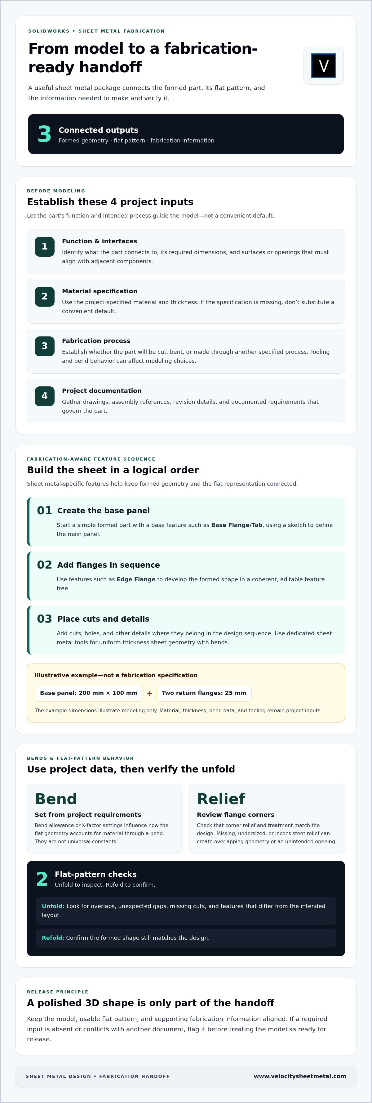
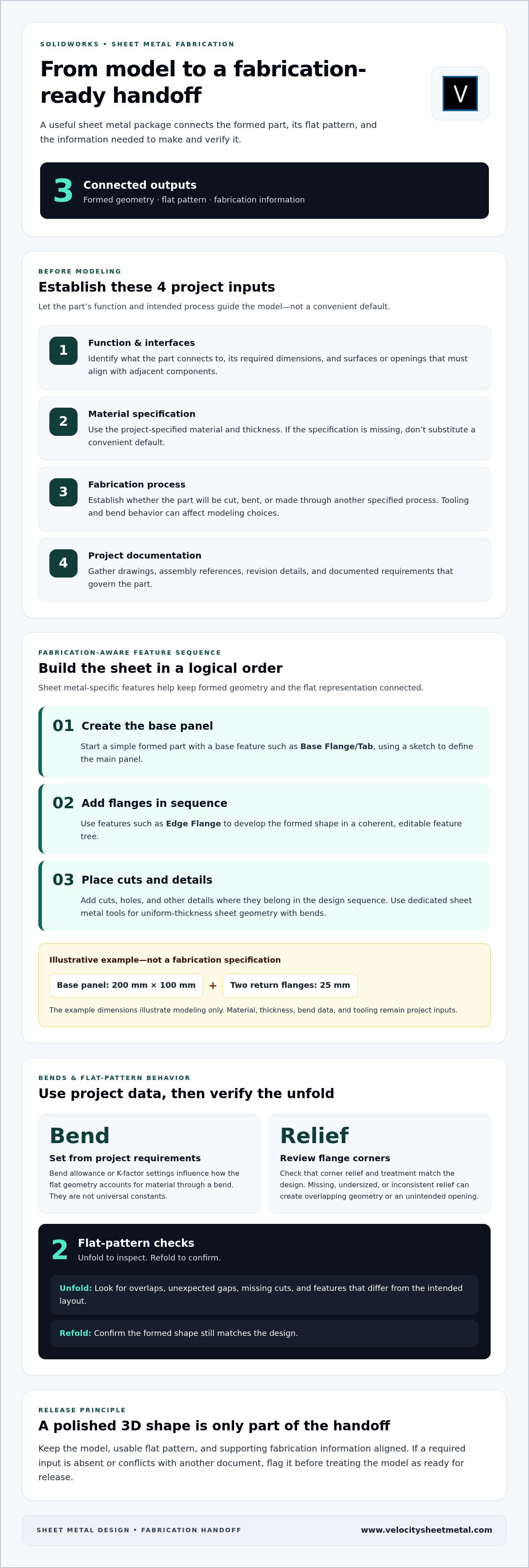
A part can look complete in a 3D view and still be difficult to fabricate. The model may not preserve how the material is formed, the flat pattern may not represent the intended part, or the handoff may leave key decisions open. Effective SOLIDWORKS sheet metal design for fabrication treats the model, its flat pattern, and its supporting information as one connected package.
What makes a SOLIDWORKS sheet metal model fabrication-ready?
A fabrication-ready sheet metal model represents the part’s material and forming intent, produces a usable flat pattern, and communicates the information needed to make and verify the part. That takes more than a polished 3D shape. A solid body can show the desired finished geometry without clearly describing how the sheet unfolds or which project assumptions govern its bends.
Build the part with coherent sheet metal features so its formed geometry and flat representation stay connected. This gives designers and fabricators a clearer basis for discussing cut features, bends, interfaces, and changes. Sheet metal is used in many applications, so the specified material and forming requirements matter. Generic settings can’t replace project information.
What to establish before you begin modeling
Start with the part’s function and the process intended to make it. A formed bracket, enclosure, or duct component may share basic geometry, but its interfaces and fabrication needs differ. Gather the information that defines those needs before creating features:
- Function and interfaces: Identify what the part connects to, its required dimensions, and any surfaces or openings that must align with adjacent components.
- Material specification: Use the project’s specified material and thickness. Don’t substitute a convenient default when the specification is missing.
- Fabrication process: Establish whether the part will be cut, bent, or formed through another specified process. Tooling and bend behavior can affect modeling choices.
- Project documentation: Gather drawings, assembly references, revision details, and documented requirements that govern the part.
Some inputs depend on the project. Bend allowance, bend radius, and other sheet metal settings should reflect the material, tooling, and production requirements for the job, not an assumed universal value. If an input is absent or conflicts with another document, flag it before treating the model as ready for release.
This preparation keeps design intent visible as you build. It also gives you a practical starting point for choosing a feature sequence that carries the part from defined requirements to a dependable flat pattern.
Build the SOLIDWORKS Sheet Metal Part in a Fabrication-Aware Feature Sequence
Once the part requirements are clear, build the model so each feature reflects how the sheet will be cut and formed. Sheet metal-specific features preserve relationships between the finished shape and its flat pattern. Modeling the same part as arbitrary solid geometry may create a convincing 3D view, but can make bend behavior and unfolding harder to manage.
Create the base shape and add sheet metal features
For a simple formed part, start with a base feature such as Base Flange/Tab, using a sketch to define the main panel. Add flanges in a logical order with features such as Edge Flange, then add cuts, holes, or other details where they belong in the design sequence. Use dedicated sheet metal tools when the geometry represents a uniform-thickness sheet with bends. Reserve general solid features for details that suit them and still preserve a valid sheet metal result.
For example, imagine a small bracket with an illustrative 200 mm by 100 mm base panel and two 25 mm return flanges. These dimensions are only a modeling example, not a fabrication specification. Material, thickness, bend data, and tooling remain project inputs. A feature tree built from the panel and its flanges is easier to revise than a collection of unrelated faces and extrusions. SOLIDWORKS describes its available tools and approaches in its SOLIDWORKS sheet metal design methods documentation. Feature names and interface steps can vary by release, so verify them against the SOLIDWORKS version used for the project.
Set bends, reliefs, and flat-pattern behavior
Define bend behavior using the project’s material and forming information. Bend allowance or K-factor settings influence how the flat geometry accounts for material through a bend. They aren’t universal constants. Use the values specified for the job and its process rather than relying on a generic default.
Review corners where flanges meet. Reliefs provide space for material at bends and corners, while the chosen corner treatment affects both formed geometry and the cut layout. A relief that is too small, missing, or inconsistent with the design can lead to overlapping geometry or an unintended opening in the flat pattern. Compare the detail with project requirements.
Then unfold the part and inspect the result. Look for overlapping regions, unexpected gaps, missing cuts, or features that appear differently than intended. Refold it and confirm the formed shape still matches the design. This is a core step in SOLIDWORKS sheet metal design for fabrication: the feature tree should support edits, and the flat pattern should represent the intended part.
Clear digital geometry supports practical cutting and forming workflows, including CNC press brake bending and custom laser cutting. Explore sheet metal fabrication capabilities as you plan the transition from model to production.
Choose the Right SOLIDWORKS Outputs: 3D Model, Flat Pattern, or Drawing
A fabrication handoff can include several files, but each should have a clear job. The 3D model communicates the formed part and how its features relate. The flat pattern shows the developed sheet geometry. The drawing adds dimensions, notes, and revision details that may not be obvious from geometry alone. SOLIDWORKS sheet metal design for fabrication is stronger when the output package matches the task, rather than simply containing every possible file.
When the 3D model, flat pattern, and drawing each help
The 3D model helps reviewers understand overall form, flange direction, openings, and how features fit together. It’s useful for design review and coordination, but geometry alone may not convey every manufacturing instruction.
The flat pattern represents the sheet in its developed state for workflows that use a cut profile. Review it for the intended outline, openings, and orientation. A flat pattern communicates geometry, but doesn’t automatically provide all dimensions, material details, or revision instructions needed for a controlled release.
The drawing can bring that context together. It can specify critical dimensions, material and thickness, notes, and revision information. Use it to make requirements visible, especially when a model view or exported profile can’t explain the design intent on its own.
Prepare a clear digital handoff for fabrication
Rule: Select outputs to match the fabrication task and the documentation the project requires. A cut profile may call for a flat-pattern file. A formed-part review may need the 3D model. A controlled release may also require a drawing. The receiving workflow determines which formats and deliverables are appropriate.
DXF is commonly used to communicate two-dimensional profile geometry, while STEP can convey three-dimensional geometry. Neither format replaces project-specific instructions, and the right choice depends on the agreed workflow. Before release, align the files and documentation around:
- Material and thickness specified for the part.
- Critical dimensions and interfaces that govern fit or assembly.
- Revision identifiers that match across the model, drawing, and exported files.
- Project notes needed to interpret the geometry or intended process.
For cut profiles, a clean flat-pattern output supports clearer coordination around custom laser cutting. The related guide, “Precision Laser Cutting Services: The 2026 Buyer’s Guide for Industrial Parts,” provides additional context on preparing parts for that workflow. Keep the package controlled: correct geometry paired with an outdated drawing can still create uncertainty at the fabrication handoff.
Check SOLIDWORKS Sheet Metal Design Before Releasing It for Fabrication
A final review catches mismatches before they travel from the CAD file into production. For SOLIDWORKS sheet metal design for fabrication, check the model and its outputs together. Separate general geometry checks from values that depend on project-specific material and tooling data.
Run a model and flat-pattern review
Unfold the part and confirm the flat pattern represents the intended design. Review bend regions, reliefs, cutouts, and outer edges for overlapping geometry, unexpected gaps, or features that are missing or altered. Refold the model to verify the formed shape still matches the design intent.
Use this release checklist before sharing files:
- Geometry: Inspect the formed part for incomplete features, unintended intersections, and unclear interfaces.
- Flat pattern: Confirm the developed outline and cut features match the intended part, with no unexpected overlaps or gaps.
- Project settings: Check material, thickness, bend allowance, and related forming values against the project specification and applicable process data. Don’t treat defaults as approved production values.
- Drawing: Verify critical dimensions, notes, material information, and interfaces are legible and consistent with the model.
- Revision control: Confirm the saved model, drawing, and exported files all identify the same released revision.
Keep the distinction clear: geometry and file consistency can be reviewed directly, while bend behavior and settings depend on the specified material and tooling. For bend-related review, the topic “Common Press Brake Forming Defects” can help frame the kinds of forming issues to watch for. Check the design’s bend details against the actual project requirements rather than assuming one setting suits every part.
Review fabrication details and documentation
Before release, compare material and thickness information with the project specification. Then check dimensions that control fit, assembly, or alignment. A model may appear correct while a drawing omits a critical interface dimension or carries an outdated note. Resolve discrepancies across the model, drawing, and export before issuing the package.
Make the review repeatable. Record the revision being released, keep only the intended deliverables in the handoff, and verify that each file opens as expected. This helps prevent a correct flat pattern from being paired with an older drawing or model.
Once the design package is aligned, discuss a fabrication project with Velocity Sheet Metal for practical sheet metal fabrication, including custom laser cutting and CNC press brake bending.
Move from SOLIDWORKS Model to Fabricated Part with a Clear Handoff
A sound CAD model is only one part of a successful production workflow. Fabrication depends on the information moving with it: the flat pattern that communicates cut geometry, the drawing that records requirements, and coordinated project data that keeps components aligned. Clear handoffs help designers, fabricators, and project teams work from the same intent instead of making assumptions at each stage.
Coordinate design information with fabrication needs
Align on deliverables early. Establish which model, flat-pattern file, drawing, material details, and revision information belong in the project package. This gives each participant a shared reference and helps expose gaps before work reaches production. A clear file structure and consistent revision identifiers also make it easier to distinguish current information from superseded files.
For mechanical projects, sheet metal parts often connect to other components and coordinated building systems. BIM coordination and spool drawings can help communicate how fabricated elements relate to the broader mechanical workflow. The model still needs clear geometry and project context, while coordination helps teams identify relationships and resolve information gaps across the handoff. For more on these digital-to-physical connections, see “BIM for Sheet Metal Fabrication: The 2026 Guide to Digital-to-Physical Workflows.”
Apply the workflow to cut and formed components
For a cut component, a clean flat pattern gives the production workflow a clear representation of the intended profile. Custom laser cutting can turn that digital geometry into a cut part, provided the released file matches the approved design and the project’s required format. Keep material and revision information aligned with the profile so the geometry stays connected to its context.
Formed components need another layer of review. Consider bend locations, reliefs, and formed geometry together so the digital part communicates the intended result for CNC press brake bending. A flat pattern alone cannot explain every forming detail, so pair it with relevant model views, drawing dimensions, and notes. The guide “CNC Press Brake Services: 2026 OEM Buying Guide” offers further context on formed-part workflows.
A reliable handoff carries design intent from model to cut, form, and coordination. That’s the practical goal of SOLIDWORKS sheet metal design for fabrication: make digital inputs clear enough to support accurate interpretation throughout production. Velocity Sheet Metal connects fabrication capabilities with coordinated project information. Discuss your sheet metal fabrication project and plan a clear path from design information to fabricated components.
Carry Design Intent Through to the Finished Part
Fabrication-ready SOLIDWORKS sheet metal design for fabrication depends on more than a complete-looking model. Build with sheet metal features that preserve forming intent, check the flat pattern against the design, and release drawings and files with consistent material, dimensions, and revision information. Each output has a job. Together, they give fabrication and project teams a clearer basis for moving from digital design to production.
That handoff connects directly to cutting, forming, and coordinating components. Velocity Sheet Metal provides custom laser cutting, CNC press brake bending, BIM coordination, and spool drawing services for fabrication workflows. Its management team has more than 50 years of combined industry experience.
To connect design information with practical fabrication needs, discuss your sheet metal fabrication project with Velocity Sheet Metal. A clear model and a coordinated handoff are strong starting points. Put them to work on your next project.
Frequently Asked Questions
Can SOLIDWORKS create a flat pattern for every sheet metal part?
No. A part needs geometry that can be unfolded into a flat sheet for SOLIDWORKS to generate a meaningful flat pattern. Parts modeled with appropriate sheet metal features are generally easier to flatten than arbitrary solid geometry. Complex transitions, intersecting bends, or features that create overlapping material may prevent a valid result. Check that the part unfolds as intended, then review the flat geometry for gaps, overlaps, and unexpected cut details.
How do I make a SOLIDWORKS sheet metal model ready for fabrication?
Build the part with sheet metal features, then confirm its material, thickness, bend behavior, and relief details against the project requirements. Unfold and inspect the flat pattern, check the formed model, and make sure the drawing clearly communicates critical dimensions and interfaces. SOLIDWORKS sheet metal design for fabrication also depends on a consistent handoff: the model, drawing, and exported files should identify the same revision and use the deliverables required by the project workflow.
What is the difference between a SOLIDWORKS sheet metal model and a flat pattern?
The sheet metal model represents the formed part in three dimensions, including its bends, flanges, and cut features. The flat pattern represents the sheet in its developed, unfolded state, showing the geometry used for suitable cutting workflows. Neither view necessarily communicates every project instruction. A drawing may still be needed for dimensions, material information, notes, and revision control. Use each output for the information it conveys best.
Which file format should I send for sheet metal fabrication?
Choose the format specified by the receiving project workflow. A DXF or DWG may be used to share two-dimensional flat-pattern geometry, while STEP can communicate three-dimensional model geometry. A native SOLIDWORKS model or drawing may also be needed for design intent and documentation. Don’t assume one file replaces the others. Match file types to the task, and check that exports correspond to the released model revision.
Why does my SOLIDWORKS sheet metal part fail to flatten?
A part may fail to flatten if its geometry or feature sequence doesn’t support unfolding. Check for intersecting bends, self-overlapping faces, problematic corner conditions, or features created as general solid geometry rather than sheet metal features. Review the base feature and bend definitions, then suppress or revise later features to help identify where the issue begins. After correcting the geometry, test the flat pattern again and inspect the result before export.
Do I need a drawing if I already have a SOLIDWORKS 3D model?
Not always, but a 3D model may not communicate all fabrication requirements on its own. A drawing can make critical dimensions, material and thickness information, notes, interfaces, and revision status explicit. Whether it’s required depends on the project’s documentation workflow and the information the fabrication team needs. If you use a model without a drawing, confirm that the required instructions are clearly provided through the agreed project documents.
How does SOLIDWORKS sheet metal design affect CNC press brake fabrication?
The model records formed geometry and bend locations, which influence how the part is interpreted for CNC press brake bending. Bend allowance, radius, reliefs, and material information should reflect project-specific process inputs, not generic assumptions. Clear bend details and consistent model, flat-pattern, and drawing revisions help reduce ambiguity during the handoff. The fabrication team needs the relevant specifications and documentation to relate the digital design to the forming process.