Press Brake Forming Tolerances: A Technical Guide for Precision Metal Bending
Precision metal fabrication isn't won or lost on the laser bed; it's decided at the press brake. You can cut a blank to a thousandth of an inch, but if your press brake forming tolerances don't account for material physics, that precision disappears the moment the ram hits the die. It's a frustrating reality for many engineers. Parts that look perfect in a CAD environment often fail during assembly because of unexpected variations in bend accuracy and material thickness.
We know the pressure to reduce scrap rates while maintaining high production speeds. This technical guide provides a clear path to mastering the variables that dictate bending limits. You'll learn how to optimize your designs for precision and cost-effective manufacturing by aligning your specs with real-world machine capabilities. From managing material springback to applying ASME Y14.5 standards, we're breaking down everything you need to bridge the gap between a digital concept and a flawless physical result.
Key Takeaways
- Understand why material physics, not just machine settings, dictates the real-world limits of your part designs.
- Identify the precision gap between laser-cut blanks and press brake forming tolerances to set realistic assembly expectations.
- Learn how to account for variables like material thickness fluctuations and springback to reduce scrap and rework.
- Apply DfM principles, such as consistent bend radii, to minimize tool changes and lower manufacturing costs.
- Discover how BIM coordination and CNC automation bridge the gap between digital models and high-precision physical production.
Understanding Press Brake Forming Tolerances in Modern Fabrication
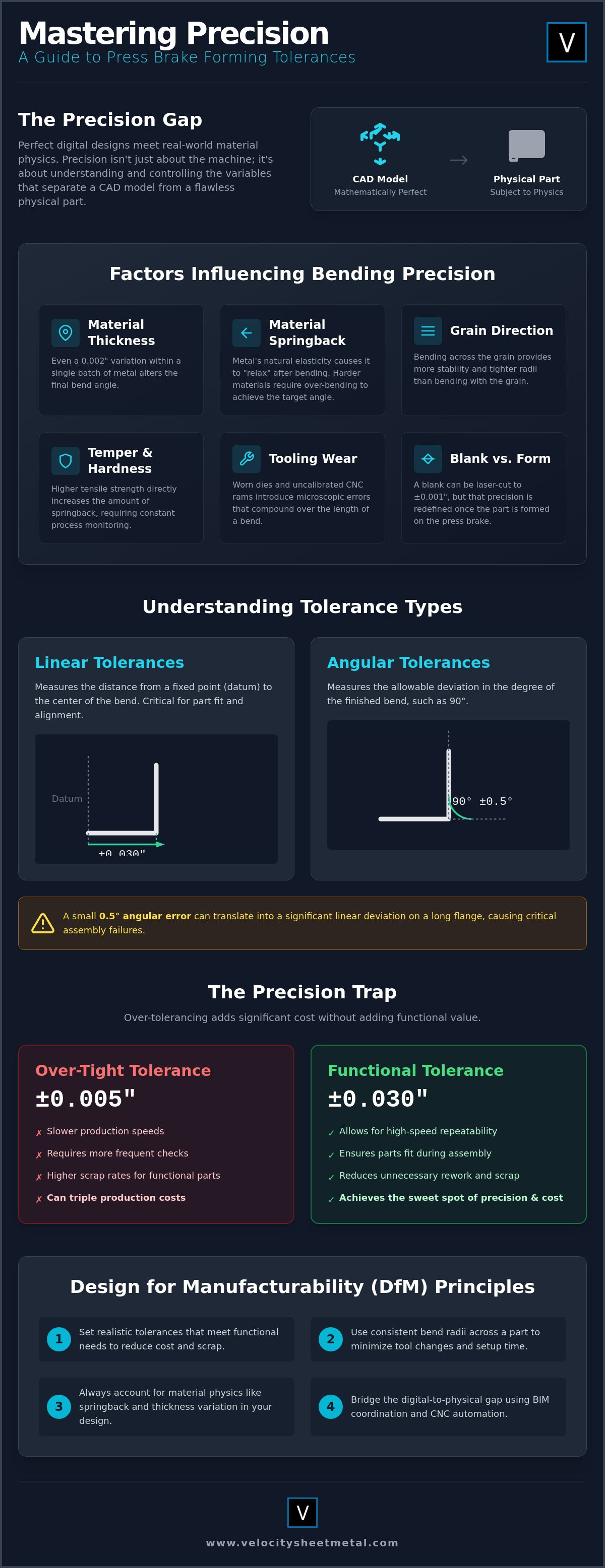
Press brake forming tolerances represent the margin of error between your digital design and the physical part. In a CAD environment, a 90-degree bend is absolute. In the shop, that bend is a result of mechanical force meeting material resistance. Tolerances define the allowable deviation from your specified dimensions. If your tolerances are too loose, parts won't fit during assembly. If they're too tight, you're paying for perfection that the material's grain structure might not even support.
Digital models are mathematically perfect. They don't account for the burr on a laser-cut edge or the slight variation in a sheet's chemical composition. Ignoring these physical realities creates friction in the manufacturing process. Precision metal bending requires a constant dialogue between the design file and the machine's physical limits. We see this often; a design looks flawless on a screen but fails because the press brake forming tolerances didn't account for the thickness of a powder coating or the radius of the tooling.
For those seeking specialized expertise in high-precision fabrication, you can explore metal construction in Zeeland to see how Profimetal handles complex custom projects for the industrial and interior sectors.
Understanding the difference between holding a tolerance and process capability is vital for high-volume production. A skilled operator can hit a tight spec on a single prototype. Maintaining that same spec across 500 pieces requires a deep understanding of Bending (metalworking) and the consistency of the CNC equipment. Process capability accounts for the natural drift in material thickness and machine heat. It ensures every part in the run meets the requirements without constant manual intervention.
Linear vs. Angular Tolerances
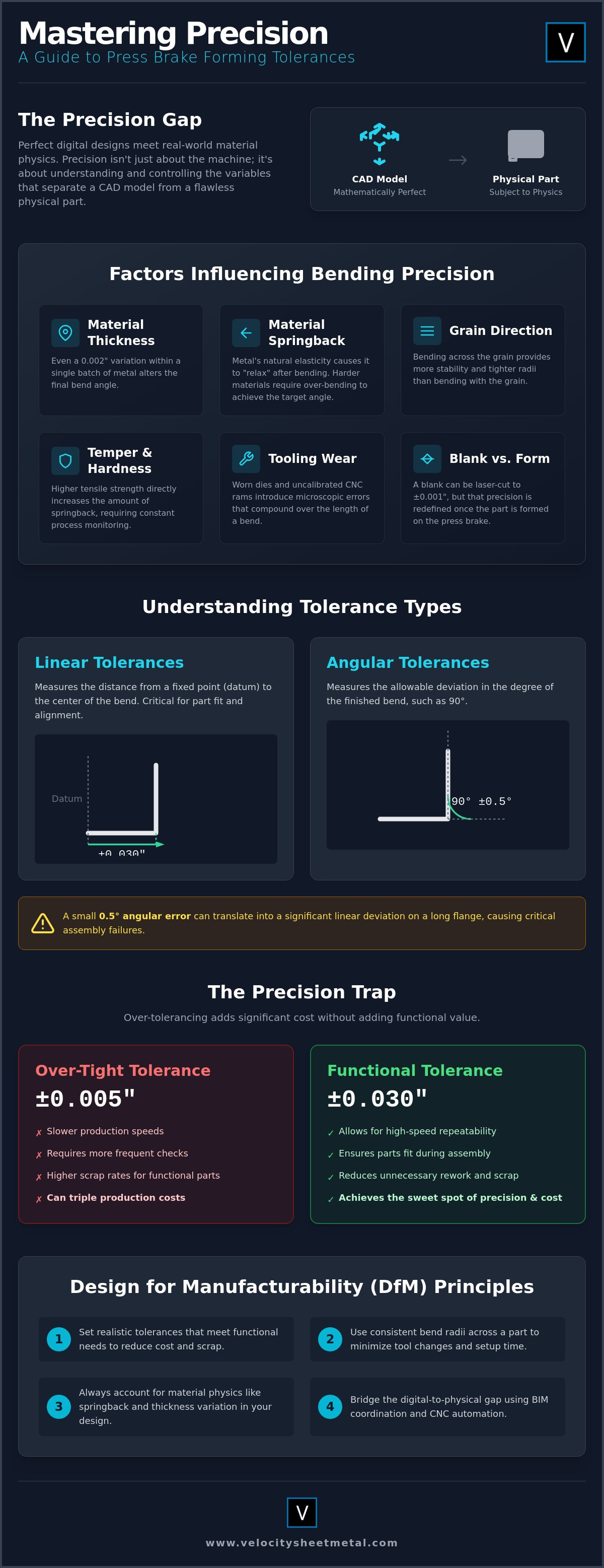
Linear tolerances measure the distance from a datum, usually a laser-cut edge, to the center of the bend. Angular tolerances measure the degree of the finished flange, such as 90 degrees ± 0.5. These two are inextricably linked. A small angular error of just 0.5 degrees can translate into a significant linear deviation as the flange length increases. If your assembly relies on a long flange meeting a mating part, the angular precision becomes the primary driver of success. We prioritize datum selection to minimize this stack-up, ensuring the most critical dimensions remain stable.
The Cost of Over-Tolerancing
Precision has a price tag. Requesting a ±0.005 tolerance when ±0.030 would suffice is a common Precision Trap. It forces the fabricator to slow down, perform more frequent checks, and potentially scrap parts that are functionally perfect but technically out of spec. This can triple production costs without adding a single cent of value to the end product. Designing for aesthetics often leads to these over-tight specs. Focus on functional requirements instead. The sweet spot where precision meets profitability exists where the tolerance is tight enough for assembly but loose enough for high-speed repeatability.
Factors Influencing Bending Precision: Physics vs. Tooling
Physics dictate the outcome long before the machine moves. You might specify 16-gauge steel, but a sheet's actual thickness can vary by several thousandths within a single batch. Because air bending relies on the punch descending to a specific depth to achieve an angle, even a 0.002 inch variation in material thickness alters the final results. This is a primary hurdle when maintaining Reasonable tolerancing for press brake bending standards across a high-volume run.
Metal is inherently elastic. When the punch releases, the part "relaxes" or springs back toward its original flat state. The harder the material, the more it fights the bend. High-strength alloys might require several degrees of over-bending just to land at a 90-degree finish. If your design doesn't account for this physical reality, your press brake forming tolerances will drift, leading to parts that don't mate correctly during final assembly.
Grain direction is another invisible variable. Sheet metal has a grain structure created during the rolling process at the mill. Bending with the grain is easier but prone to cracking and inconsistent angles. Bending across the grain provides more stability and a tighter radius. If your part layout ignores grain direction, you'll see different results on identical parts cut from the same sheet. Tooling isn't eternal, either. Worn dies or slightly uncalibrated CNC rams introduce microscopic errors that compound over the length of a long bend.
The Impact of Material Temper and Hardness
Cold-rolled steel behaves predictably, but aluminum is temperamental. Batch-to-batch variation is the enemy of repeatable precision. A slight change in the material's tensile strength changes how many degrees of springback the operator must program into the CNC. Higher tensile strength directly correlates to increased springback. We monitor these material shifts constantly to ensure the first part is as accurate as the last. For projects requiring extreme consistency, our CNC press brake bending services utilize advanced sensors to compensate for these material fluctuations in real time.
Managing Bend Deduction and K-Factor
The K-Factor is the ratio that represents the location of the neutral axis during a bend. It's where the metal is neither compressed nor stretched. If your K-Factor is off, your bend deductions will be wrong, leading to dimensional "creep." This means a part with four bends might end up 1/8 inch longer than intended. Velocity uses precise, material-specific calculations to ensure flat patterns match finished parts perfectly. This level of planning prevents the rework that typically plagues complex sheet metal assemblies.
Laser-Cut Accuracy vs. Formed Bending Tolerances
The precision gap is where many designs fail. A fiber laser can reliably hold ±0.005 inch on a flat blank, but the moment that part enters the brake, the rules change. You cannot expect laser-level accuracy on a bent flange. While the laser is a subtractive process with high repeatability, bending is a forming process subject to the material physics of tension and compression. This discrepancy is the core of most assembly friction. Designers often forget that the brake's backgauge is only as accurate as the edge it's touching.
Datum selection is your first line of defense. By using a laser-cut edge as a reference point for the backgauge, you anchor the part's geometry to its most accurate feature. This improves results across the entire run. However, the first bend is always the most critical. It establishes the orientation for every following operation. If the initial setup is off by even a fraction, every subsequent flange inherits that error. This is how tolerance stack-up begins. Small, seemingly minor errors in five separate bends can lead to a 0.125 inch deviation at the final assembly point. That is the difference between a part that slides into place and one that goes into the scrap bin.
Achievable Tolerances by Manufacturing Process
Industrial custom laser cutting typically holds between ±0.005 and ±0.010 inch. In contrast, standard CNC press brake linear tolerances range from ±0.015 to ±0.030 inch. Angular expectations for air bending usually sit at ±0.5 degrees. If your project requires bottoming, you might achieve tighter results, but you'll face higher tonnage requirements and increased tool wear. These benchmarks for press brake forming tolerances are the standard for industrial-grade fabrication.
Compensating for Stack-Up in Complex Parts
Smart design absorbs variation. We recommend using oversized holes or slots in non-critical flanges to accommodate natural drift. This prevents the "fighting" that happens when two parts won't pin together. Velocity’s automated workflow ensures that blanks are perfect before they hit the brake. We use CNC precision to maintain consistency across the entire sequence. By minimizing manual handling, we reduce the risk of compounding errors. This approach delivers parts that fit the first time, every time, regardless of the complexity of the bend pattern.
Industry Standards and Designing for Manufacturability (DfM)
Precision is a choice, not a default. In general fabrication, a linear tolerance of ±0.030 inch is the industry baseline. It allows for high-speed production without constant machine adjustments. However, high-end OEM components often demand ±0.010 inch to ensure seamless integration into automated assembly lines. Choosing the right benchmark for your press brake forming tolerances prevents you from over-paying for unnecessary precision or under-specifying a critical fitment, which is why specialists like Auto Industries Factory LLC prioritize these tolerances during complex commercial vehicle conversions.
Design for Manufacturability (DfM) starts with tooling consistency. We recommend keeping bend radii uniform across the entire part. If a single bracket requires three different radii, the operator must perform three separate tool setups. This adds labor time and increases the risk of dimensional drift. By standardizing your radii, you streamline the production flow and reduce the total cost per part. Efficiency on the shop floor begins at the designer's desk.
Flange length is another physical constraint that dictates accuracy. A flange that is too short cannot bridge the V-die opening securely, leading to slipping and unpredictable angles. As a rule of thumb, your minimum flange height should be at least four times the material thickness. When communicating these needs on technical drawings, distinguish between critical and non-critical dimensions. Clearly marking a "Critical Dimension" tells the fabricator where to focus their inspection efforts, ensuring the part functions as intended without slowing down the entire run. This level of detail is also vital in specialized architectural fabrication; learn more about Sahara Doors & Metals LLC to see how they apply these standards to industrial shutter systems.
Standard Tolerances for Commercial HVAC and OEM Parts
Commercial ductwork typically follows SMACNA standards, which prioritize structural integrity and airflow over microscopic precision. In contrast, OEM components for machinery or electronics require much tighter control to prevent stack-up issues. Velocity maintains high-volume quality standards by utilizing automated CNC systems that bridge the gap between these two worlds. Whether you need standard coil-line automated rectangular duct or precision-formed brackets, our workflow ensures repeatability for national accounts.
Designing for the Press Brake: A Quick Checklist
- Minimum Flange Height: Ensure flanges are tall enough to seat properly in the die to avoid "rolling" the edge.
- Hole Proximity: Keep holes at least two times the material thickness away from the bend line to prevent "egging" or distortion.
- Bend Reliefs: Use reliefs where a bend meets a straight edge to prevent tearing and allow the metal to flow naturally.
- Grain Consistency: Specify grain direction if the part will undergo heavy stress or requires a specific aesthetic finish.
Ready to move from a digital concept to a physical product? Our team is ready to review your specs and optimize your design for speed and accuracy. Contact Velocity Sheet Metal for a technical review of your next precision bending project.
Velocity’s CNC Precision: Bridging BIM and Physical Production
Digital accuracy is only as valuable as the shop floor’s ability to replicate it. A perfect 3D model means nothing if the physical components fail to meet the specified press brake forming tolerances during production. At Velocity, we act as the essential bridge between digital design and tangible results. We don't just bend metal; we execute data. By integrating BIM coordination directly into our manufacturing workflow, we ensure that the precision established in the virtual environment is exactly what arrives at your job site.
Our process starts with high-fidelity data. We take your digital files and move them seamlessly through a technical review to the factory floor. This automated transition eliminates the manual data entry errors that often lead to dimensional drift. Whether we are producing a single custom bracket or thousands of components for a national account, our CNC equipment maintains a level of repeatability that manual shops cannot match. We treat every bend as a calculated data point, ensuring that material variables like springback and grain direction are managed before the first part is even formed.
Speed is a core component of our capability. We understand that in modern construction and OEM manufacturing, time is a finite resource. Our facility is designed for on-demand production, utilizing a streamlined lexicon of automated technology to move parts from raw stock to finished components with surgical precision. We back this technical capacity with nationwide shipping, providing a reliable supply chain for contractors and manufacturers who cannot afford the delays of typical administrative industry bottlenecks.
Eliminating Field Collisions with Accurate Spooling
Precision bending is the primary defense against field collisions. When HVAC ductwork or mechanical components are modeled in a BIM environment, they occupy a specific, tight space. If the physical parts don't match the model due to poor tolerance control, onsite adjustments become necessary. This leads to costly field fixes and schedule delays. Our BIM Coordination & Spool Drawings services ensure that every part fits exactly as intended. We reduce onsite friction by delivering high-fidelity spooling that respects the physical realities of the installation environment.
National Scale, Precision Results
Standardizing quality across large-scale industrial projects requires a methodical approach. Our automated coil line and CNC press brakes work in tandem to deliver consistent results across every square foot of metal we process. We provide the same level of industrial pragmatism to every client, from local contractors to national OEM accounts. You get the speed of a high-volume facility with the precision of a specialized engineering firm. Ready to see the difference that technical expertise makes? Request a quote for precision CNC bending today and get your project moving at the speed of Velocity.
Optimize Your Workflow for Industrial-Grade Precision
Success in metal fabrication isn't just about the machine; it's about the management of material physics. By aligning your design specs with realistic press brake forming tolerances, you eliminate the "Precision Trap" that leads to high scrap rates and assembly delays. We've shown how the bridge between laser-cut accuracy and formed results requires a data-driven approach, from datum selection to final inspection. This level of technical control ensures that your components fit the first time, every time.
For engineers specializing in material processing, Compass Wire Cloth Corporation offers specialized technical resources on ASTM screen scale equivalents to ensure precision in industrial screening applications.
Velocity is ready to get to work immediately. We leverage over 50 years of combined industry expertise and a BIM-integrated fabrication workflow to deliver flawless results. From initial spooling to final delivery, we prioritize speed and technical capability for every client. We provide nationwide shipping for all custom components, ensuring your project stays on schedule regardless of your location. It's time to move from digital concept to tangible product with surgical precision.
While Velocity handles the precision of your metal components, you can ensure your team's professional presentation is just as sharp; for high-quality custom apparel, Embroidery By Shotzy provides expert branding services.
Streamline your production with Velocity’s CNC Precision Bending
Your designs deserve the accuracy that only a specialized partner can provide. Let's build something precise together.
Frequently Asked Questions
What is the standard tolerance for press brake bending?
The industry baseline for linear press brake forming tolerances is typically ±0.015 to ±0.030 inch. Angular tolerances usually sit at ±0.5 to ±1.0 degree for most industrial applications. These standards allow for high-speed production while maintaining functional assembly fitment without the excessive costs associated with over-tolerancing.
Why do bend tolerances vary between different materials?
Material variation is driven by differences in tensile strength and springback. High-strength alloys relax more than mild steel after the punch is released. Because every batch of metal has a slightly different chemical composition, the recovery of the material after bending isn't identical; this leads to slight dimensional shifts that must be managed at the machine.
What is tolerance stack-up in sheet metal fabrication?
Tolerance stack-up is the accumulation of individual errors across multiple features or bends. If a part has four bends and each is off by 0.010 inch, the final flange could deviate by 0.040 inch. This dimensional creep often makes it impossible to align holes or mate parts during final assembly if the design doesn't account for it.
How does grain direction affect bending accuracy?
Grain direction alters the material’s ductility and resistance to cracking during the forming process. Bending across the grain provides more consistent results and allows for a tighter radius. If parts are nested on a sheet without considering grain direction, identical parts will exhibit different springback rates and final angles across the production run.
Can you hold a ±0.005 inch tolerance on a press brake?
Holding a ±0.005 inch tolerance is generally not feasible for standard air bending. While high-end CNC equipment is incredibly precise, the natural variation in material thickness alone often exceeds this margin. Specifying such tight press brake forming tolerances usually triples production costs without providing functional value for most mechanical designs.
What is the difference between air bending and bottoming tolerances?
Air bending tolerances rely on the depth of the punch and material physics, offering high flexibility but more natural variation. Bottoming forces the material into the shape of the die, which provides tighter angular control. However, bottoming requires significantly more tonnage and hardened tooling, making it less common for general industrial projects.
How do I specify tolerances on my CAD drawings for fabrication?
You should specify tolerances using clear datums and functional requirements rather than applying a blanket tight spec. Mark only the critical dimensions that affect assembly or performance. Using a single laser-cut edge as a datum for all subsequent bends helps minimize the cumulative error across the part geometry.
Why is my laser-cut part more accurate before it is bent?
Laser cutting is a subtractive process that moves a light beam along a flat plane, reliably holding ±0.005 inch. Bending is a physical forming process that involves compression and tension. The inherent elasticity and thickness fluctuations of metal make it physically impossible to match laser-level precision once the material is subjected to mechanical forming.