HVAC Spool Drawings for Prefabrication: From BIM Model to Fabrication

A coordinated BIM model isn’t automatically ready for the shop. HVAC spool drawings for prefabrication translate that model into a controlled handoff, showing what to fabricate, how duct sections connect, and which dimensions guide production.
That distinction matters. Model views help teams coordinate the system, but fabrication crews need clear, usable details. Missing dimensions or connection information can interrupt production, while late model changes can leave drawing sets out of step with current project conditions. Clear revisions and a shared source of truth help keep coordination and fabrication aligned.
This article explains what HVAC spool drawings need to communicate, how they support ductwork prefabrication, and how to prepare a cleaner handoff from coordinated model to fabrication. It covers spool breakdowns, dimensions, connections, and revision control, with practical checks to help teams spot ambiguity before drawings reach the shop.
Key Takeaways
- HVAC spool drawings for prefabrication turn coordinated design information into a practical reference for shop production and assembly.
- Project requirements shape drawing detail and conventions, so align the handoff before preparing spools for release.
- A coordinated BIM model and fabrication drawings serve different purposes; model views may not communicate every shop-level requirement.
- Use a pre-release review to catch unclear identifiers, dimensions, connection details, and revision status before they reach production.
- See how BIM coordination and spool drawings connect with automated rectangular duct and spiral and round duct fabrication.
What HVAC Spool Drawings for Prefabrication Show, and Why They Matter
An HVAC spool drawing is a project-specific fabrication and assembly reference developed from coordinated design information. It divides ductwork into identifiable sections and shows the information the shop needs to make and prepare them for assembly. Depending on project requirements, a drawing may include component types, dimensions, connection details, identifiers, and relationships to adjoining ductwork.
A BIM model coordinates the system in context; a spool drawing communicates how a defined section of that system is to be fabricated and assembled. The model helps teams review a duct route alongside surrounding building systems. The drawing package focuses on production: what belongs to each spool, how its parts connect, and how the section can be identified as it moves through the work. Building Information Modeling (BIM) provides a digital approach to representing building information, but the fabrication handoff still needs to make shop-level requirements clear.
That distinction is central to HVAC spool drawings for prefabrication. A coordinated model is an important input, not an automatic substitute for a production-ready reference. Spool drawings support prefabrication, but they don’t replace ongoing project coordination or installation planning. If the duct route changes, update the affected drawing information to match the coordinated design and current revision.
How spool drawings fit into commercial HVAC work
Mechanical contractors, engineers, detailers, and fabrication teams contribute at different points in a commercial HVAC project. Clear spool references give these participants a shared way to identify duct sections and understand how they fit together. For example, a drawing can distinguish a rectangular duct section from an adjoining transition or fitting, then show how the assembly connects along the planned route. Consistent identifiers help teams track sections through production and delivery.
Drawing conventions and identification methods vary by project. The key is making it possible for everyone using the package to connect each reference to the intended ductwork without guessing. Clear references keep fabrication information tied to coordination decisions.
What prefabrication changes about the drawing handoff
With prefabrication, duct sections are prepared away from the area where the system will ultimately be assembled. Shop teams therefore need actionable information before production begins, especially dimensions and connection details that define the parts and their relationships. A model view may show where a duct run sits in the building; a fabrication drawing must make the relevant section understandable as a discrete piece of work.
Prefabrication shifts more planning into the digital-to-shop handoff. It doesn’t remove the need to coordinate or plan installation; it makes clear references and current information essential earlier in the process. Project requirements determine the necessary drawing detail, so agree on those expectations before releasing a package.
How HVAC Spool Drawings Move from BIM Coordination to Fabrication
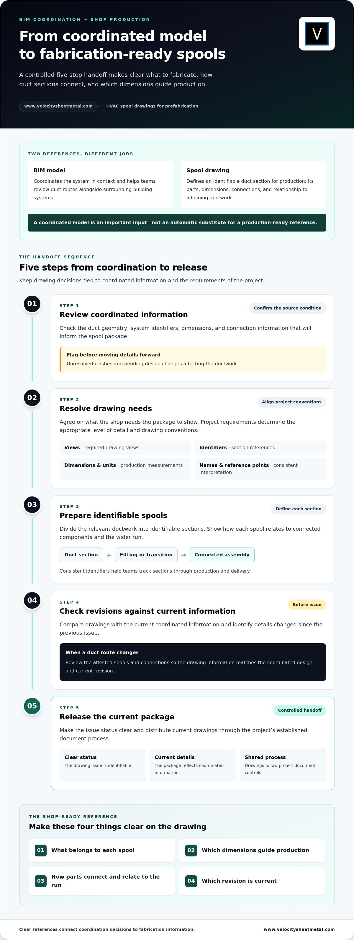
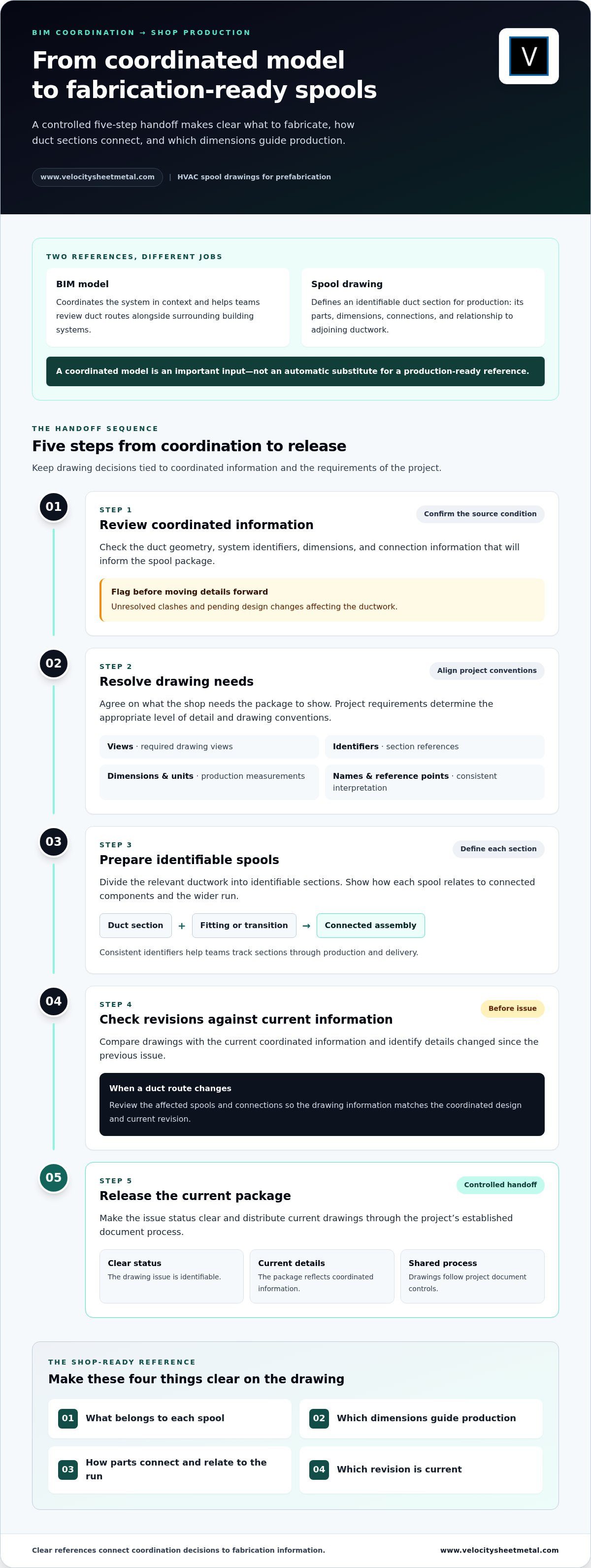
A fabrication package takes shape through a controlled sequence, not a direct export from a model. Teams establish which design information is coordinated, define what the drawings must show, prepare the spool views, verify revisions, and release the package for production. This keeps drawing decisions tied to project requirements rather than assumptions about what every shop needs.
- Review coordinated information. Confirm the duct geometry, system identifiers, dimensions, and connection information that will inform the spool package. Flag unresolved clashes or pending design changes before affected details move forward.
- Resolve drawing needs. Agree on required views, identifiers, dimensions, units, naming conventions, and reference points. Project requirements determine the appropriate level of detail and drawing conventions.
- Prepare the spools. Divide the relevant ductwork into identifiable sections and show how each section relates to connected components and the wider run.
- Check revisions. Compare the drawings with current coordinated information and identify details that changed since the previous issue.
- Release the package. Make the issue status clear and distribute current drawings through the project’s established document process.
Each step has a clear purpose. If a design change affects a duct route, for example, review the spools and connections it touches before releasing those drawings. For broader context on the digital-to-physical process, see BIM for sheet metal fabrication.
Inputs that help establish a usable spool package
Start with coordinated geometry, system identifiers, dimensions, connection details, and the project’s drawing requirements. Consistent units, names, and reference points help detailers and fabrication teams interpret each spool the same way. If a clash remains unresolved or a design change is in progress, flag it before releasing the affected detail. The package should reflect the intended coordinated condition, not an assumption about how an open issue will be resolved.
Project standards also shape how information is presented. For example, the VA HVAC Design Manual provides design and construction procedures that include drawing guidance for its projects. Align drawing conventions with the applicable project requirements rather than treating one format as universal.
Drawing checks before release to the shop
Review each sheet for dimensions, views, labels, connection details, and consistency with the coordinated model. Confirm identifiers are legible and adjoining duct sections can be related without guesswork. Make the revision identifier and issue status easy to find on each drawing, not only in a separate transmittal.
Keep revision status visible from drawing issue through production, so the shop can distinguish current information from superseded details. This matters when changes arrive after a package has been prepared. Velocity Sheet Metal connects BIM coordination and spool drawings with ductwork fabrication. Explore the BIM coordination and spool drawing workflow.
Spool Drawings vs. BIM Model Views: What Fabrication Teams Need
A coordinated model does not automatically communicate every shop-level requirement. It can show duct geometry in relation to the building, but a fabrication team may still need selected views, annotations, and identifiers arranged around the work it must produce. Neither deliverable universally replaces the other. The project workflow and requirements determine how model views and spool drawings work together.
Use the model to understand spatial context and coordination. Use fabrication-focused drawings to present the information needed to interpret and produce defined duct sections. This distinction helps teams avoid treating a visually complete model as a complete production package.
| Aspect | BIM model views | Spool drawings |
|---|---|---|
| Purpose | Show ductwork within the coordinated building system. | Organize selected ductwork information for fabrication and assembly. |
| Typical users | Design, engineering, and coordination teams. | Detailers and fabrication teams, with project participants using the references as needed. |
| Information emphasis | Spatial relationships, routing, and surrounding systems. | Defined sections, dimensions, component identifiers, and connection relationships. |
| Production use | Supports coordination and design review. | Supports shop interpretation and production, according to project requirements. |
When a model view is not enough for production
A model may display a multi-piece duct run with several transitions and connections, yet the overall view may not make each piece easy to identify or inspect. A fabrication sheet can isolate the relevant run, arrange views for legibility, and add annotations that identify components and relationships the shop needs to interpret. The goal isn’t to duplicate the model. It’s to make selected information easier to act on.
A view of the full run can establish where it travels, while focused drawing views clarify how separate sections relate at transitions. Without that organization, a reader may need to search through the model or infer which details apply to a particular piece. HVAC spool drawings for prefabrication bridge that gap by arranging information around production tasks.
What a fabrication-focused view should clarify
A useful view should make orientation, dimensions, component identification, and connection relationships understandable together. Readers need to distinguish the section being fabricated from adjacent ductwork and see how the parts relate. Drawing requirements vary, so align the presentation with the project’s conventions instead of assuming one universal format.
Keep responsibilities clear: design information establishes the intended system, while fabrication drawings communicate selected production details. Questions that affect design intent still belong in coordination; a drawing shouldn’t resolve them through an unsupported assumption. For additional context on factors that shape fabrication decisions, review this HVAC duct fabrication procurement guidance.
How to Prepare HVAC Spool Drawings for a Cleaner Prefabrication Handoff
A reliable handoff depends on more than a complete-looking drawing set. Before releasing HVAC spool drawings for prefabrication, check that each sheet reflects coordinated geometry, identifies its ductwork clearly, and carries the right revision status. A consistent review helps teams catch gaps while they can still be corrected in the documents.
A concise pre-release checklist for drawing packages
Use this checklist as a final review. Adapt it to the project’s requirements and drawing conventions rather than treating it as a universal specification.
- Confirm coordinated geometry. Check that the duct route and represented components match the current coordinated design. Flag unresolved coordination items instead of relying on assumptions.
- Identify each spool. Make sure every section has a clear reference that can be followed across the drawing package and related project information.
- Review views and labels. Confirm the views are legible and relevant to the work, and that labels help readers distinguish the spool and its components.
- Verify dimensions. Check that shown dimensions are clear and consistent with the coordinated design and applicable project requirements.
- Check connections. Ensure the drawing communicates how the spool relates to adjoining ductwork and its connections.
- Confirm issue status. Remove superseded sheets from the active issue set or mark them clearly so they can’t be mistaken for current production information.
Review the package as a set, too. Consistent identifiers, units, naming, and reference points make it easier to move between sheets without reinterpreting how the information is organized. If a reviewer can’t tell which view or dimension applies to a spool, resolve that ambiguity before release.
Managing revisions without creating field confusion
Changes are part of project coordination. Confusion starts when a change appears in one reference but not another, or when teams can’t distinguish the current issue from an earlier one. Use a simple sequence to keep affected details aligned:
- Log the change. Record what changed and identify the duct sections, connections, and drawing references it may affect.
- Review the impact. Check the coordinated design and identify each affected spool drawing. Keep open coordination items separate from details that are ready for fabrication.
- Update and compare. Revise affected drawings and model references consistently, then review the changed information against the current coordinated condition.
- Issue clearly. Show the revision identifier and status on the relevant drawings. Remove outdated sheets from the active package or mark them as superseded.
Production teams need to recognize current information at a glance. Don’t let an unresolved design question look like an approved fabrication detail. Track the open item until it’s resolved, then update and issue the affected references together. This helps prevent conflicting information as work moves forward.
For a coordinated path from drawings to sheet metal production, explore Velocity Sheet Metal’s BIM coordination and spool drawing services.
How Velocity Sheet Metal Connects HVAC Spool Drawings with Fabrication
A useful spool drawing package connects coordinated project information to the realities of sheet metal production. Velocity Sheet Metal provides BIM coordination and spool drawings alongside HVAC ductwork fabrication, bringing those parts of the workflow together. Project-specific drawing information can be considered in the context of the ductwork being prepared for the shop.
This connection matters across different duct types. Velocity Sheet Metal’s production capabilities include automated rectangular duct and spiral and round duct and fittings. Each project has its own routing, components, and drawing requirements, so the handoff should reflect the coordinated design and the information needed for the relevant fabrication work. Drawings support production planning; they don’t replace broader project coordination or installation planning.
Good BIM coordination connects digital project information to physical ductwork production through a handoff the project team and fabrication team can interpret. That practical focus is central to preparing HVAC spool drawings for prefabrication. It keeps drawing decisions tied to the specific work rather than relying on generic assumptions about every project’s package or requirements.
A coordinated handoff from project information to sheet metal production
Aligning drawing coordination with the production context gives teams a clearer path from model information to fabrication references. The project’s geometry, identifiers, connection information, and drawing conventions all influence what the handoff needs to communicate. A spool package for one duct arrangement may need different views or references than another. Shape the detail around project requirements rather than treating it as a fixed deliverable for every job.
Velocity Sheet Metal’s BIM coordination and spool drawing work sits alongside its sheet metal production capabilities, including automated rectangular duct and spiral and round duct and fittings. The management team brings more than 50 years of combined industry experience, informing a practical understanding of the steps between coordinated information and physical production.
Velocity Sheet Metal serves customers nationwide and offers nationwide shipping. Clear, usable project information helps as ductwork moves from digital coordination to fabrication and through project logistics. A well-prepared handoff gives the people involved a consistent reference, even when coordination, shop work, and delivery involve different teams.
Plan the next step around project requirements
Before discussing a project, organize the current model information, drawing requirements, and revision status. Note which ductwork is in scope, identify open coordination items, and distinguish current references from superseded information. This helps focus the conversation on actual spool drawing and fabrication needs.
Bring the requirements together, then discuss how BIM coordination, spool drawings, and the relevant ductwork fabrication can connect for your project. Talk with Velocity Sheet Metal about your project.
Align the Next Project Decision
A stronger handoff starts before the next drawing package is assembled. Set a clear decision point for who owns drawing conventions, how coordination changes will be communicated, and when affected details are ready to move forward. That alignment gives each team a shared path from project information to production without relying on assumptions.
As you prepare HVAC spool drawings for prefabrication, treat the package as a working connection between digital design and the shop floor. Bring current project information and open questions into the planning conversation. This helps clarify what the drawings need to communicate for your ductwork and how the fabrication handoff should work.
Velocity Sheet Metal connects project teams with BIM coordination, spool drawings, and sheet metal production. Discuss your HVAC spool drawing and fabrication needs with Velocity Sheet Metal to plan the handoff for your project.
Frequently Asked Questions
Can HVAC spool drawings be revised after fabrication begins?
Yes, but a revision after production starts needs a clear impact review. Identify which spools or components are affected, compare their status with work already completed, and communicate the current issue before more work proceeds on changed details. Keep superseded information distinct from active drawings. With HVAC spool drawings for prefabrication, timely revision control helps teams identify what needs updating without treating every change as if it affects the entire package.
What causes mismatches between HVAC spool drawings and field conditions?
Mismatches can come from late design changes, outdated drawing references, unrecorded site adjustments, or differences between assumed and actual reference points. A duct route might be coordinated around an opening that later shifts, for example, while the drawing still reflects the earlier arrangement. Clear change communication helps, but teams should also compare current project information with observed conditions and resolve discrepancies through the project’s coordination process before relying on affected details.
Should HVAC spool drawings include duct supports?
Include support information when the project scope and coordination requirements call for it. Support locations can affect how ductwork relates to nearby structure and other systems, so omitting relevant information may leave a coordination question unresolved. However, don’t assume a spool drawing defines support design or structural requirements by default. Establish which team owns that information and whether it belongs in the fabrication package, a separate drawing, or another project reference.
How should HVAC spool drawings be numbered?
Use a consistent, unique identifier that lets project participants distinguish each spool and locate its related drawing. A project might organize references by system, area, or sequence, but the exact convention should follow project document standards. Keep the spool identifier stable when a drawing revision changes, and show revision information separately. That makes it easier to discuss a specific duct section without confusing its identity with the status of its latest drawing.
Do HVAC spool drawings show installation sequence?
They can communicate sequence if the project requires that information, but don’t assume every spool drawing defines how ductwork must be installed. A package may identify relationships between sections without setting their field assembly order. If sequence affects handling, access, or connection planning, make that need explicit and coordinate it with the team responsible for installation planning. Keep fabrication details and sequence guidance clearly distinguished so readers know what each reference is intended to convey.
What information should accompany an HVAC spool drawing package?
Provide enough project context for recipients to identify the package, its intended scope, and its current status. Useful accompanying information may include a drawing index, issue date or revision record, applicable project references, and a list of open items that are not released for production. Include units and naming conventions where they help interpretation. The project’s document-control process should make clear which package is active and how later revisions will be distributed.
Can spool drawings support HVAC prefabrication across multiple project sites?
Yes. A consistent drawing approach can support work across multiple sites, provided each package clearly identifies the project, site, system, and relevant revision. Keep site-specific geometry and references distinct enough that teams don’t apply one location’s details to another. Shared conventions can make packages easier to interpret, while each site’s coordinated information remains the basis for its own drawings. This supports consistent document handling without assuming the buildings or duct layouts are identical.