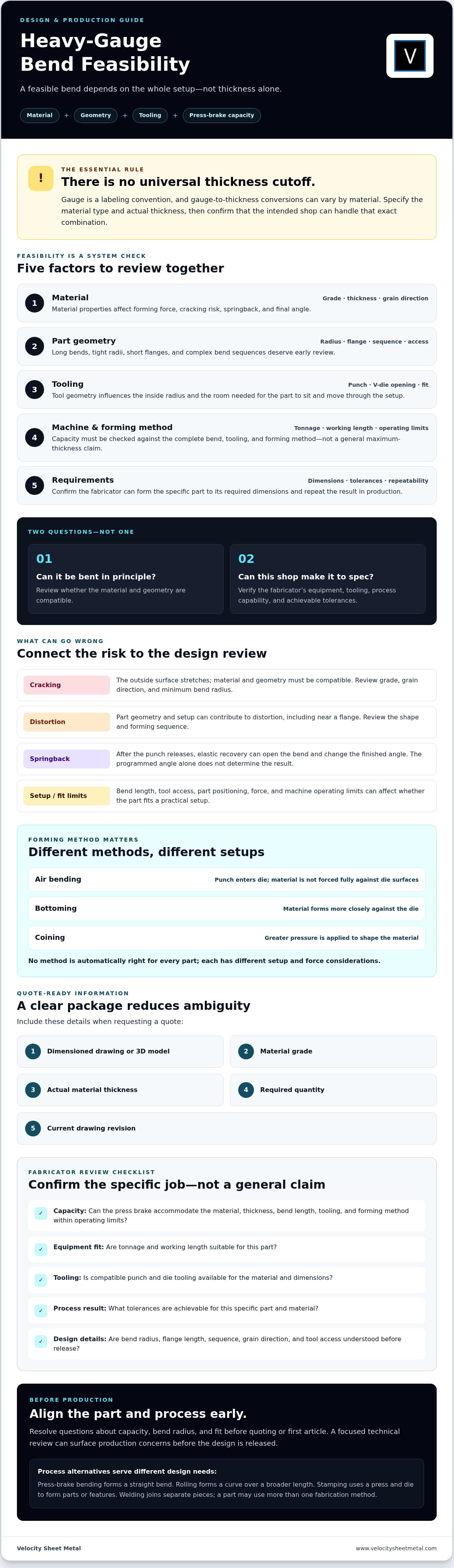
Heavy Gauge Sheet Metal Bending: Capabilities, Limits, and Design Choices
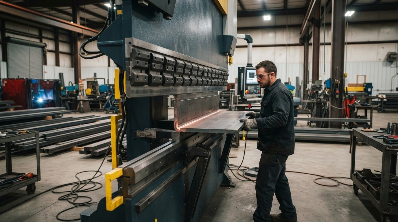
More press-brake tonnage doesn’t automatically make a bend feasible. In heavy gauge sheet metal bending, material grade, thickness, bend length, tooling, and part geometry all need to work together. A part can look straightforward on a drawing yet crack at the outside radius, distort near a flange, spring back beyond the target angle, or exceed the machine’s practical setup limits.
Resolve questions about capacity, bend radius, and fit before production, not after a quote or first article. Assess the material and geometry against the press brake, tooling, and tolerance requirements. No single thickness number answers every feasibility question.
This guide explains the variables that affect heavy-gauge bend feasibility and design choices that can help reduce cracking, distortion, and springback. You’ll learn what to include in a production-ready drawing package, which details to clarify before quoting, and what to ask a CNC press-brake fabricator about tonnage, bed length, tooling, supported materials, and achievable tolerances. The goal is to align the part and process before production begins.
Key Takeaways
- Heavy gauge sheet metal bending has no universal thickness cutoff. Assess material, geometry, tooling, and machine capacity together.
- Compare bend radius, flange length, bend sequence, and tool access before finalizing part geometry.
- For a clearer quote, provide a dimensioned drawing or 3D model, material grade, thickness, quantity, and current revision.
- Ask a CNC press-brake fabricator to confirm equipment fit and achievable tolerances for your specific part and material.
- A focused technical review can surface production concerns before the design is released.
What Heavy Gauge Sheet Metal Bending Means for Part Design
Heavy-gauge bending forms relatively thick sheet or plate. Feasibility depends on the material, part geometry, tooling, and press-brake capacity, not on a universal thickness cutoff. A thickness that one shop can bend in a particular material and bend length may not suit another shop’s equipment or tooling.
Separate two questions: Can the material and geometry theoretically be bent? And can a specific fabricator form the part to its required dimensions and repeat that result in production? The first is a design question. The second requires a review of the shop’s equipment, tooling, and process capability.
Why “heavy gauge” has no universal cutoff
Gauge is a labeling convention, not a complete material specification. Gauge-to-thickness conversions can vary by material, so a gauge callout alone may leave room for interpretation. Identify the material type and actual thickness on the drawing and purchase documents. If a gauge-to-thickness conversion is proposed, verify it against the specified material before release.
Thickness alone doesn’t determine feasibility. Material properties, bend length, geometry, tooling, and machine capacity interact. Confirm that the intended shop can accommodate the specific combination rather than relying on a general maximum-thickness claim.
Where press-brake bending fits in fabrication
In press-brake bending, a punch presses the workpiece into or against a die to form a straight bend. The forming method and setup affect the bend angle and resulting shape. Material may also spring back after the force is removed. The overview of Bending (metalworking) explains common methods such as air bending, bottoming, and coining, along with basic forming concepts.
This process differs from rolling, which forms a curve over a broader length, and stamping, which uses a press and die to form parts or features. Welding joins separate pieces rather than bending one workpiece. These processes suit different design needs, and a part may use more than one fabrication method.
For a closer look at the process and the information to discuss with a supplier, consult the CNC Press Brake Services buyer guide. Velocity Sheet Metal offers CNC press-brake bending, but its available information doesn’t specify heavy-gauge capacity. Confirm press-brake fit against the actual drawing and requirements before releasing the job.
How Material, Thickness, and Tooling Affect Heavy Gauge Bends
Successful heavy gauge sheet metal bending depends on how the material responds to a specific setup. Grade and thickness influence the force needed to form a bend, while grain direction and geometry can affect cracking risk, springback, and the final angle. Treat these variables as a system, not as separate checks.
Material behavior, bend radius, and springback
Springback is the material’s elastic recovery after the punch releases. The bend can open slightly, leaving the final angle different from the angle formed under load. The amount varies with material behavior, thickness, bend radius, and forming method, so don’t assume the programmed angle alone determines the finished part.
The outside surface of a bend stretches and may crack if the material and geometry aren’t compatible. Grain direction can also affect forming response. Confirm any grain-direction requirements, minimum bend radius, and material-grade details against the material specification and with the fabricator before locking the design.
Tooling, press-brake capacity, and forming method
The punch contacts the sheet and helps define the bend, while the V-die opening supports the material as it forms. Their geometry influences the inside radius and the space needed for the part to sit and move through the setup. A different punch or die may change the bend result, but tooling must also suit the material, dimensions, and forming method.
In air bending, the punch pushes material into the die without forcing it fully against the die surfaces. Bottoming forms the material more closely against the die, while coining applies greater pressure to shape it. Each method has different setup and force considerations. None is automatically right for every part.
Press-brake capacity must be checked against the complete bend: material properties, thickness, bend length, tooling, forming method, and the machine’s operating limits. Have the fabricator verify force calculations and confirm tonnage, working length, compatible tooling, and safe operating limits for the specific job.
When the design may need a different approach
Long bends, tight radii, short flanges, and complex bend sequences deserve early review. They can affect required force, tool access, part positioning, or the ability to form later bends without interference. For example, a flange may be too short to sit securely in the selected die, or a previously formed leg may obstruct the punch.
Flag these conditions before production. A fabricator can review the drawing and discuss whether a radius, flange, sequence, or other design detail should change. The right adjustment depends on the application, material, and fit requirements. For broader manufacturing context, the Fabricators & Manufacturers Association (FMA) shares resources for the fabrication industry.
If your design is ready for a capability review, discuss the drawing and requirements with Velocity Sheet Metal. The company offers CNC press-brake bending, but equipment fit and tolerances need to be confirmed for the actual part before release.
Heavy Gauge Bending: Compare Design Tradeoffs Before Release
A bend that looks simple in a flat pattern can create constraints after forming. Before release, compare the geometry with the part’s functional needs and the fabricator’s confirmed tooling and process capability. Tight radii, short flanges, and bends near cutouts aren’t automatic deal breakers, but each deserves a specific review.
| Design feature | Potential tradeoff | Check before release |
|---|---|---|
| Inside bend radius | A tighter radius may increase material strain or limit suitable tooling. | Confirm the radius against material requirements, fit, and available tooling. |
| Flange length | A short flange may be difficult to position or support in the selected die. | Dimension the flange and bend location from consistent datums. Ask the fabricator to review minimum flange needs. |
| Bend sequence | Earlier bends can obstruct tool access or interfere with later forming steps. | Review the sequence against part clearance and repeatability. |
| Access and nearby features | Holes, slots, cutouts, or adjacent legs may distort or collide with tooling. | Check clearances, feature locations, and assembly access against the formed geometry. |
Bend radius and flange geometry
The specified inside radius affects material strain, tooling selection, and how the finished part fits against mating components. State the radius clearly rather than leaving it to assumption. Dimension flange lengths and bend locations from consistent datums so the shop can interpret the drawing without guessing. Minimum flange guidance depends on the material, thickness, tooling, and process. Request a fabricator review rather than relying on a universal rule.
Bend sequence, holes, and assembly
Forming order can change whether the punch and die can reach a bend and whether the part can be positioned consistently. Check holes, slots, and cutouts near bend lines for potential distortion or tooling interference. Then review the formed part alongside mating components, fasteners, coatings, and assembly clearances. Distinguish a cosmetic preference, such as a particular radius or bend appearance, from a functional requirement for fit, strength, or assembly.
For potential forming issues to inspect during design review, see the guide to common press brake forming defects. It can help focus attention on features likely to affect the finished part.
When to revise geometry or production plans
Compare the cost of preserving the current design with the impact of adjusting a radius, extending a flange, adding relief, or changing the bend sequence. A revision may improve tool access or reduce a forming concern, but it must still meet the part’s functional requirements. If the geometry remains difficult to form, discuss other production approaches with a qualified fabrication partner. Base the decision on the drawing, material, application, and confirmed shop capabilities, not a one-size-fits-all rule.
Prepare a Heavy Gauge Sheet Metal Part for an Accurate Quote
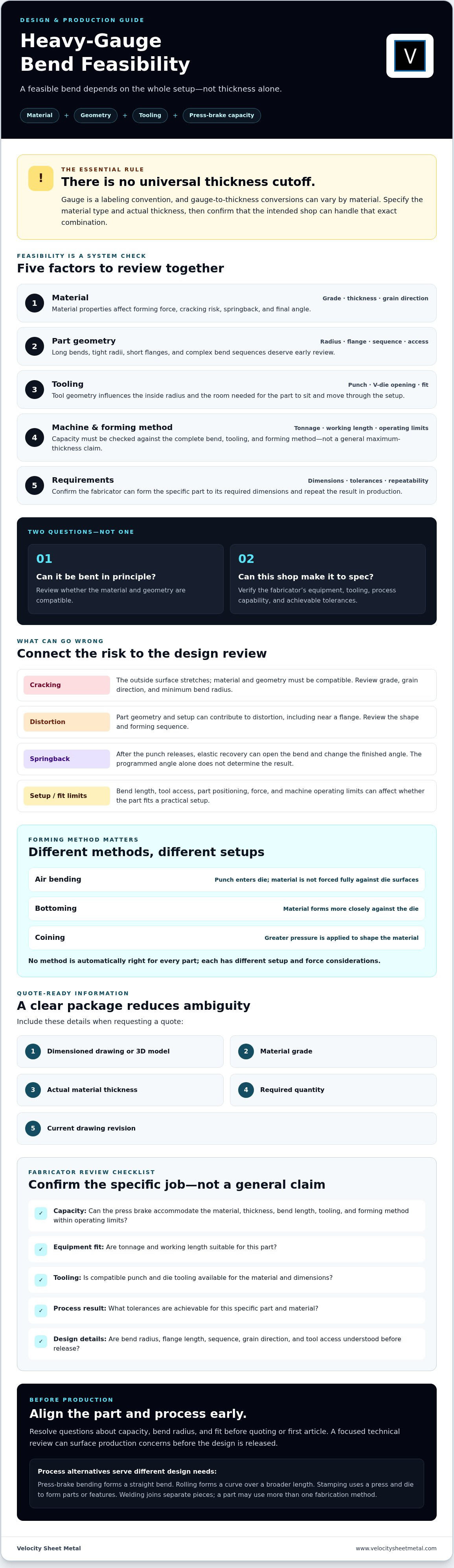
A useful quote starts with enough information to evaluate the part, not just its material thickness. For heavy gauge sheet metal bending, the drawing, specifications, quantity, and revision need to describe the same production intent. Use this checklist to prepare a clear request and identify open questions before release.
- Define the requirement. State the part’s function, critical fit or assembly interfaces, quantity, and any surface or appearance requirements.
- Provide a controlled drawing or model. Send a dimensioned drawing or 3D model with units, a clear revision identifier, and consistent datums.
- Specify the material. Identify the material grade and actual thickness. Include grain-direction requirements where they apply, and flag assumptions that need confirmation.
- Define the bends and features. Call out bend angles, inside radii, flange lengths, bend locations, holes, slots, and cutouts. Make critical dimensions easy to identify.
- Set acceptance criteria. State functional tolerances, surface requirements, and inspection expectations where applicable. Don’t assume a blanket tolerance or inspection method.
- Confirm production feasibility. Ask the fabricator to review equipment capacity, working length, tooling, part size, bend sequence, and other constraints against the complete design.
A fabricator can review a bend when you provide a controlled drawing or model, material grade and thickness, quantity, bend dimensions, functional tolerances, and revision status. Add known concerns or application requirements. Clear inputs help distinguish firm requirements from preferences that may be open to adjustment.
Resolve questions before release
Ask whether the press brake and tooling suit the material, part size, and bend sequence. Confirm which material assumptions and achievable tolerances the shop can support, and request written clarification for critical requirements. Agree on how design questions, drawing revisions, samples, and production approvals will be handled. This keeps everyone working from the same version.
Before approval, compare the model with the drawing notes. Check that the material, thickness, dimensions, bend details, and revision match. Resolve conflicts directly rather than relying on an unstated default. A focused review can also help prevent press-brake forming defects by surfacing unclear dimensions or process concerns before production.
Velocity Sheet Metal offers CNC press-brake bending, but material ranges, machine capacity, and tolerances must be confirmed for the specific part. Discuss your bending requirements with Velocity Sheet Metal, using the drawing and specifications as the starting point.
Choose a CNC Press-Brake Partner for Heavy Gauge Bending
A capable bending partner should do more than confirm that a press brake is available. For heavy gauge sheet metal bending, the shop needs to assess the specific material, part dimensions, bend geometry, tooling, and required tolerances together. Treat general capacity statements as a starting point, not confirmation that your part can be produced as drawn.
What a capable bending partner should clarify
Look for direct answers and a defined review process. Before committing, confirm:
- Equipment fit: Can the available tonnage and working length accommodate the material and bend length?
- Tooling: Is suitable punch and die tooling available for the specified radius, flange, and forming method?
- Design constraints: Could part size, bend sequence, or access affect forming or repeatability?
- Requirements: Which tolerances, material assumptions, and inspection expectations can the shop support, and which need written confirmation?
- Coordination: How will drawing questions, revisions, sample review, and production approval be handled?
Confirm capacity, tolerances, and production details against your actual drawing. Be cautious of unsupported claims or lead-time commitments that don’t account for the material and part requirements.
How Velocity Sheet Metal fits the fabrication workflow
Velocity Sheet Metal offers CNC press-brake bending and serves customers nationally, with nationwide shipping. Its management team brings more than 50 years of combined industry experience. That experience is useful context for a technical conversation, but it doesn’t replace confirming machine fit, supported materials, and achievable tolerances for a specific job.
For OEM buyers, a CNC press-brake services for OEMs buyer guide can help frame questions to ask when assessing a fabrication partner. Keep the focus on documented requirements and clear communication from drawing review through production coordination.
Move from drawing review to next steps
Prepare the current drawing or model, material specification, quantity, revision status, and critical fit or inspection requirements. Ask the shop to review the information and confirm capacity, tooling, tolerance expectations, and open production questions before you commit. Resolve assumptions early, while design changes are still manageable.
Discuss your sheet-metal bending project with Velocity Sheet Metal by sharing the part requirements for review.
Turn Your Bend Design Into a Production-Ready Plan
Successful heavy gauge sheet metal bending starts with a complete part review, not a gauge label alone. Material grade, thickness, bend geometry, tooling, and press-brake capacity must align. Clear drawings, defined tolerances, and early confirmation of equipment fit help reduce uncertainty before production.
Velocity Sheet Metal offers CNC press-brake bending, precision sheet metal fabrication, custom laser cutting, and BIM coordination. The company serves customers nationally and ships nationwide. Specific material ranges, machine capacity, and achievable tolerances still need to be confirmed against your part requirements.
Bring the drawing, material specification, quantity, and critical fit requirements into the conversation. Discuss your sheet-metal bending project with Velocity Sheet Metal to start a production review.
Frequently Asked Questions
What thickness is considered heavy gauge sheet metal?
There’s no universal thickness that defines heavy gauge sheet metal. “Heavy gauge” is a context-dependent fabrication term, and gauge-to-thickness conversions can vary by material. Specify the material type and actual thickness on the drawing and purchase documents rather than relying on a gauge label alone. Whether a thickness is considered heavy for a particular job also depends on bend length, geometry, tooling, and the press brake being considered.
Can a press brake bend heavy gauge sheet metal?
Yes, a press brake can bend heavy gauge sheet metal if the machine, tooling, material, and part geometry are compatible. Capacity depends on more than thickness: material properties, bend length, tooling, and forming method all affect the setup. Ask the fabricator to assess the actual drawing and confirm machine tonnage, working length, tooling, supported material range, and operating limits before treating a part as producible.
How do you calculate the force needed for a heavy gauge bend?
Estimate the required force using the material’s properties, thickness, bend length, die opening, and forming method. These inputs interact, so a calculation should match the intended tooling and process rather than use thickness alone. Treat online charts or calculators as preliminary guidance, then have the fabricator verify the force against the specific machine and setup. Confirm that the required bend fits the press brake’s operating limits.
What causes springback in heavy gauge sheet metal bending?
Springback occurs when material elastically recovers after the punch releases, causing the bend angle to open from its formed position. Its effect depends on the material, thickness, bend radius, and forming method. A press-brake setup may account for that response, but the finished angle still needs to meet the part’s requirements. Identify critical angles and tolerances on the drawing, then confirm how the fabricator will evaluate them.
What is the minimum bend radius for heavy gauge sheet metal?
There’s no single minimum bend radius for every heavy-gauge part. The workable radius depends on material grade, thickness, grain direction where relevant, tooling, and the part’s functional needs. A radius that’s too tight may increase strain or cracking risk, while a larger radius can affect fit. Specify the required inside radius and ask the material supplier or fabricator to review it against the material specification and forming setup.
What information should I send for a heavy gauge sheet metal bending quote?
Send a dimensioned drawing or 3D model with its revision status, units, material grade, actual thickness, and quantity. Include bend angles, inside radii, flange dimensions, critical interfaces, tolerances, surface requirements, and inspection expectations where applicable. Note grain direction or other material requirements if they matter. Complete information lets a fabricator assess tooling, machine fit, bend sequence, and open design questions before confirming feasibility or preparing a quote.
Can holes or slots be placed close to a bend?
Sometimes, but placement depends on the feature’s size and location, material behavior, bend geometry, tooling, and the required finished dimensions. A hole or slot too close to a bend may distort during forming or interfere with the punch, die, or part positioning. Dimension the feature from a clear datum and flag it as critical if needed for assembly. Ask the fabricator to review its location against the formed part before releasing the design.