BIM Model to Fabrication Accuracy: A Technical Guide for Mechanical Contractors

Why does a "clash-free" digital model so often result in a pile of mis-fabricated rectangular duct once it hits the job site? You've likely seen it happen. The coordination looks perfect on screen, but inaccurate spool drawings lead to costly field rework and wasted material. It's a common frustration for mechanical contractors working under tight project schedules that leave no room for manual re-interpretation. You need your digital files to translate into physical components with surgical precision. Achieving high BIM model to fabrication accuracy isn't just about the software; it's about the integration of data with the machines that cut and bend the steel.
This technical guide shows you how to bridge the gap between digital coordination and shop-floor execution to eliminate waste. You'll learn the steps to create a seamless digital-to-physical workflow that ensures zero-clash installation. We'll preview how tools like Revit 2027 and automated coil lines work together to keep your timelines predictable. From the initial digital concept to the final physical result, we'll show you how to turn your BIM data into a tangible competitive advantage and a more profitable project.
Key Takeaways
- Identify the technical "broken handoff" where design models fail and learn how to maintain fidelity from the digital concept to the physical component.
- Master the core drivers of BIM model to fabrication accuracy by ensuring critical metadata like gauge, material, and lining travels seamlessly with the geometry.
- Transition from simple coordination BIM to fabrication-ready models that account for actual construction requirements, including specific connectors and seams.
- Adopt a technical workflow using manufacturer-specific Revit families and a fabrication-focused BEP to drive automated shop machinery with surgical precision.
- Discover how integrating BIM coordination with automated coil-line production enables predictable timelines and zero-clash installation for high-volume national projects.
The Digital-to-Physical Gap in HVAC Fabrication
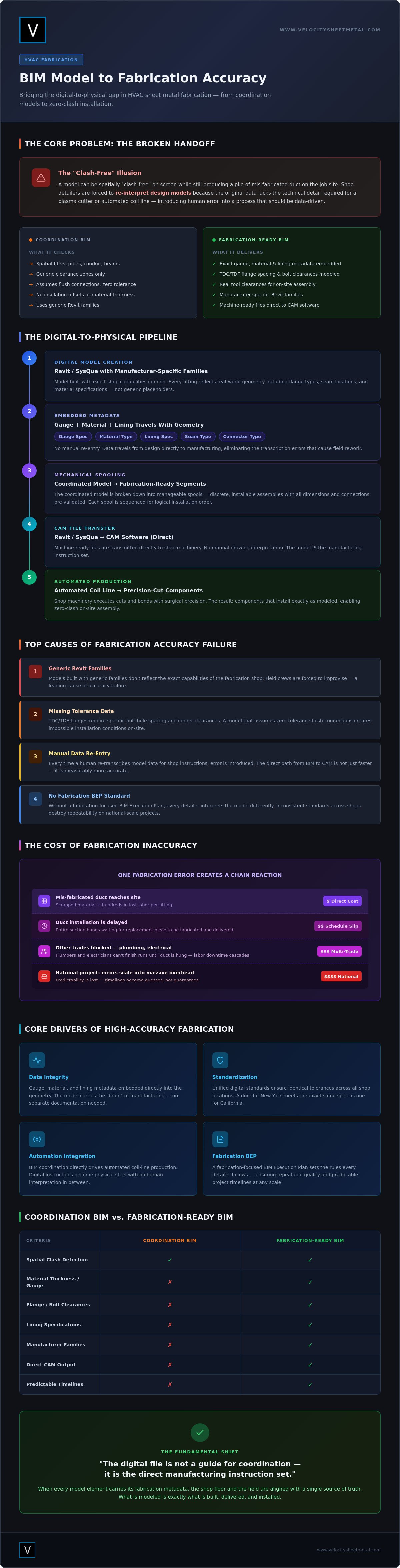
The industry often mistakes a high-resolution 3D rendering for a buildable plan. While Building Information Modeling (BIM) provides the necessary framework for modern construction, BIM model to fabrication accuracy is the true measure of a project's technical success. This accuracy represents the fidelity between a digital coordinate and a physical piece of steel. When this fidelity breaks, you experience the "broken handoff." This occurs when shop detailers must re-interpret design models because the original data lacks the technical detail required for a plasma cutter or an automated coil line. This gap doesn't just create extra work; it introduces human error into a process that should be driven by data.
Closing this gap requires a shift in how we view the digital file. It isn't just a guide for coordination; it's the direct set of instructions for manufacturing. By implementing a dedicated workflow for BIM for sheet metal fabrication, contractors can move from reactive field fixes to proactive shop-floor precision. This transition ensures that what is modeled is exactly what is built, delivered, and installed.
Why Coordination Does Not Equal Fabrication
Coordination models typically focus on spatial relationships. They ensure the ductwork fits in the ceiling alongside pipes, conduits, and structural beams. However, "fitting" is not the same as "building." Many coordination models ignore material thickness, insulation offsets, and specific flange allowances. A software "clash-free" status is meaningless if it doesn't account for the physical tool clearances needed for on-site assembly. For example, a TDC/TDF flange requires specific spacing for corners and bolts. If the model assumes a flush connection with zero tolerance, the installer faces an impossible task. Relying on generic Revit families instead of manufacturer-specific content is a primary cause of BIM model to fabrication accuracy failures. If the model doesn't reflect the exact capabilities of the fabrication shop, the field crew will eventually have to improvise.
The Economic Impact of Fabrication Errors
Inaccuracy carries a heavy price tag that goes far beyond the cost of a single piece of metal. A field-modified transition fitting can cost hundreds in lost labor and scrapped material. These errors never happen in a vacuum. Rework cascades through other trades; plumbers and electricians can't finish their runs until the duct is hung correctly. This creates a ripple effect of labor downtime and schedule delays that can't be recovered. On national projects, these small errors scale into massive overhead. The hidden cost of manual re-interpretation is the loss of predictability. When the shop floor and the field aren't aligned with the digital model, project timelines become guesses rather than guarantees.
Core Drivers of BIM-to-Fabrication Accuracy
High-fidelity production starts with data integrity. For a model to be fabrication-ready, it must carry more than just geometric dimensions. It requires embedded metadata. This includes specific gauge requirements, material types, and lining specifications that travel directly with the 3D geometry. When this data is missing, the "brain" of the project is disconnected from the "muscle" of the shop floor. Research into BIM in Modular Construction highlights that the primary benefit of digital integration is the reduction of manual re-entry. By moving machine-ready files from Revit or SysQue directly into CAM software, you eliminate the human error inherent in manual data transcription. This seamless transition is the foundation of BIM model to fabrication accuracy.
Standardization is equally critical, especially for national accounts. Repeatable quality depends on having a unified set of digital standards that every shop detailer and machine operator follows. This ensures that a rectangular duct produced for a project in New York meets the exact same tolerances as one produced for a site in California. By establishing these rigorous digital-to-physical protocols, contractors can scale their operations without sacrificing precision. Partnering with an expert provider like Velocity Sheet Metal ensures these standards are met across every project phase.
The Role of Mechanical Spooling Services
Spooling is the tactical breakdown of a coordinated model into fabrication-ready segments. A "spool" represents a manageable, shippable unit of fabrication designed for efficient transport and rapid on-site assembly. Utilizing professional mechanical spooling services allows contractors to shift labor from the unpredictable field environment to a controlled shop setting. This process reduces on-site man-hours and minimizes the risk of installation errors. When spools are detailed with precise connection points and lifting lugs, the field crew spends less time measuring and more time hanging duct.
Automated Fabrication and Tolerances
The automated coil line is the workhorse of modern HVAC production, but its speed is only an asset if the inputs are perfect. Automated coil-line rectangular duct production relies on precise digital files to set notches, seams, and fold lines. Even a slight deviation in the digital input can lead to a cumulative error across a large run of duct. Maintaining strict tolerances also extends to CNC press brake bending and custom laser cutting. These machines operate with surgical precision, but they are bound by physical constraints. A successful workflow includes a feedback loop where the shop floor informs the BIM team of these constraints, such as minimum bend radii or tool clearances. This ensures the BIM model to fabrication accuracy remains intact throughout the entire production cycle, from the first digital cut to the final bend.
Coordination-Only BIM vs. Fabrication-Ready BIM
Coordination-only BIM is a baseline. It focuses on spatial relationships and ensures the ductwork "fits" within the ceiling alongside other trades. It stops at clash detection. Fabrication-ready BIM goes much deeper. It focuses on how the component is actually built. This distinction is where BIM model to fabrication accuracy is either won or lost. If your model doesn't account for the physical reality of seams, connectors, and tool clearances, it isn't ready for the shop floor. Design intent is a suggestion; fabrication reality is the requirement.
Contractors must demand BIM integrated fabrication shop workflows to ensure this transition is seamless. This isn't just about moving a file from one person to another. It's about a technical handoff where the digital data directly informs the manufacturing process. When the coordination team and the fabrication shop use the same standards, the risk of field rework vanishes. You move from guessing to knowing.
Anatomy of a Fabrication-Ready Model
A fabrication-ready model is a digital twin of the physical product. It includes every technical detail necessary for production.
- True-to-size fittings: Models must include insulation thickness and outer wrap dimensions to ensure actual clearances in tight corridors.
- Accurate flange types: TDC, S&D, and slip-on flanges must be modeled to scale. These connectors change the effective length of duct segments and affect how pieces mate on-site.
- Integrated supports: Hanger locations and support structures should be baked into the model to allow for pre-installation of anchors before the duct even arrives.
The "Single Source of Truth" Myth
The idea of a single, static model is a myth. A model must evolve as it moves from the engineer to the fabricator. Revisions are inevitable as field conditions change or material availability shifts. The key is managing those changes without breaking the digital thread. If the model isn't updated to match the coil line duct fabrication output, the on-site installation will fail. The shop floor's automated machinery requires exact data. If the digital file and the machine output diverge, the project schedule suffers. Real-time synchronization between the BIM team and the production line is the only way to maintain a true source of truth that actually works in the field.

Achieving 100% Accuracy: A Technical Workflow
Consistency is the enemy of field rework. To reach 100% precision, you must establish a BIM Execution Plan (BEP) that prioritizes fabrication deliverables over simple design intent. This document acts as the technical contract for the project. It defines the software versions, file exchange protocols, and coordination schedules. Within this framework, teams must utilize manufacturer-specific Revit families for both rectangular and spiral duct. These families aren't just shapes; they contain the specific mechanical properties and dimensional constraints of the shop's equipment. This ensures that every digital component is a perfect match for the physical machine. To secure your project's success, partner with Velocity Sheet Metal for integrated BIM and fabrication support.
Automated clash detection is the next critical step. Standard clash tests often fail because they only look for hard intersections between steel. A fabrication-focused workflow implements "soft" clash detection that accounts for insulation thickness and required maintenance zones. If a technician can't reach a bolt or a flange because the duct is too close to a wall, the BIM model to fabrication accuracy has failed. By baking these physical realities into the digital review, you eliminate the "it fit in the model but not in the field" excuse.
Level of Development (LOD) Standards for Sheet Metal
The difference between a "good" model and a "buildable" model lies in the Level of Development. While LOD 350 is sufficient for basic coordination, fabrication requires LOD 400. At LOD 350, parts are represented with approximate sizes and shapes. LOD 400 includes all necessary information for fabrication, including welds, bolts, and specific connectors. This higher standard provides the level of detail needed to drive an automated coil line or a precision laser cutter without manual intervention. It's the only way to ensure BIM model to fabrication accuracy remains consistent across high-volume production runs.
Field Verification and Scan-to-BIM
Digital precision is useless if the site data is wrong. This is especially true in renovation projects where "as-built" drawings are often outdated or incorrect. Implementing 3D laser scanning allows you to capture existing conditions with millimeter precision. This point cloud data is then integrated into the BIM environment through a Scan-to-BIM workflow. This process aligns the digital model with actual field conditions, preventing the #1 cause of ductwork rework: inaccurate site measurements. Statistics from industry reports show that projects using BIM-enabled prefabrication can reduce construction time by 20–50%, provided the initial field data is verified through these technical methods.
Velocity Sheet Metal: Scaling Precision with Integrated BIM
Velocity Sheet Metal operates as the technical bridge for mechanical contractors who cannot afford field errors. We transform digital coordination into tangible results. By leveraging 50+ years of combined industry experience, we've developed a workflow where BIM is the brain and our automated coil line is the muscle. This synergy is what maintains BIM model to fabrication accuracy through every phase of production. We don't just "make duct"; we execute a digital strategy that eliminates the administrative and technical delays common in traditional fabrication. Our team acts as an authoritative expert operator, equally comfortable in a high-level VDC meeting or overseeing a high-speed production run.
Our facility is optimized for speed and surgical precision. We utilize automated coil-line rectangular duct production to meet the demands of high-volume projects without sacrificing quality. For specialized needs, our custom laser cutting and CNC press brake bending handle complex fittings and OEM components that standard shops can't execute. Because we offer nationwide shipping, national accounts can finally standardize their HVAC requirements across multiple states. This ensures every job site receives the same high-caliber product, regardless of geography. We focus on efficiency and technical capability so you can focus on your project's bottom line.
From Spool Drawings to the Shop Floor
The transition from a digital file to a physical component must be seamless. Our process begins by ingesting contractor models directly into our manufacturing environment. We generate precise BIM Coordination & Spool Drawings that serve as the final, unchangeable blueprint for our machines. By using direct-to-machine data transfer, we eliminate the manual entry errors that typically plague the fabrication process. Every piece of automated ductwork undergoes rigorous quality control protocols to ensure it matches the digital specification exactly. This methodical approach guarantees that what you see in the model is exactly what arrives on your flatbed. We cut through the typical industry delays with a "can-do" attitude grounded in modern manufacturing reality.
Partnering for National Success
Scaling a mechanical contracting business requires predictable results and repeatable quality. We support your growth by standardizing HVAC ductwork fabrication for consistent multi-site delivery. Our system ensures that the technical specifications of your national account are preserved across every order. Whether you're managing a single local build or a multi-state rollout, our VDC-ready fabrication ensures your field crews spend their time installing rather than fixing. We act as your reliable, tech-savvy partner, obsessed with the details of delivery so you don't have to be. Ready to eliminate field rework? Contact Velocity Sheet Metal for BIM-integrated fabrication.
Drive Project Profitability with Fabrication-Ready BIM
Transitioning from coordination-only models to a fabrication-ready workflow is the only way to safeguard your project schedule. True BIM model to fabrication accuracy relies on the seamless integration of high-fidelity data and automated machinery. By implementing LOD 400 standards and field verification, you turn the digital model into a definitive instruction set for the shop floor. This eliminates the manual re-interpretation that causes material waste and labor downtime. You move from reactive field fixes to proactive shop-floor precision.
Velocity Sheet Metal acts as your essential digital-to-physical partner. We leverage 50+ years of industry expertise and full automated coil-line capabilities to deliver precision at scale. Our national shipping and account support ensure that your multi-state projects maintain a consistent standard of excellence. It's time to move beyond design intent and embrace the speed of automated reality. We focus on the technical details so you can focus on delivery.
Get a Quote for BIM-Integrated HVAC Fabrication and start your next project with total technical confidence. We're ready to build.
Frequently Asked Questions
What is the difference between coordination BIM and fabrication BIM?
Coordination BIM focuses on spatial relationships to ensure different trades don't clash within the ceiling or service zones. Fabrication BIM goes deeper by including technical manufacturing data like specific seams, flange allowances, and tool clearances. Achieving high BIM model to fabrication accuracy requires moving beyond simple clash detection to include these physical construction details. This ensures the shop floor receives a buildable set of instructions rather than just a geometric guide.
How does LOD 400 impact the accuracy of sheet metal fabrication?
LOD 400 provides the high-fidelity detail required for direct manufacturing, such as specific bolt patterns, weld locations, and precise connector types. While lower levels of development are sufficient for general layout, they lack the data needed to drive automated shop equipment. High-precision fabrication requires this granular level of information to ensure that every piece of ductwork fits perfectly on-site without manual modification or costly field rework.
Can BIM models be used directly to drive automated coil lines?
Yes, fabrication-ready models drive automated coil lines by exporting data directly to CAM software. This digital-to-physical handoff eliminates manual data entry and the human error that comes with transcription. By using manufacturer-specific content within the model, the software calculates the exact notches, folds, and seams required. This process turns digital spool drawings into physical ductwork with surgical precision and industrial speed.
What are the most common causes of inaccuracy when moving from model to shop?
Inaccuracy often stems from using generic Revit families that don't reflect actual shop tolerances or specific tool clearances. Another major cause is the "broken handoff" where design intent is re-interpreted by shop detailers without a unified standard. Failing to perform field verification on renovation projects also leads to models that look perfect on screen but don't match the physical constraints of the existing building structure.
How does 3D laser scanning improve fabrication accuracy?
3D laser scanning captures the exact dimensions of a job site with millimeter precision, creating a point cloud that serves as a digital twin. This data allows the BIM team to coordinate ductwork against actual "as-built" conditions rather than outdated architectural drawings. Integrating these scans into the workflow is the most effective way to maintain BIM model to fabrication accuracy in complex environments where manual field measurements are difficult to verify.
Why are spool drawings essential for mechanical contractors?
Spool drawings are essential because they act as the tactical blueprint for both the shop floor and the installation crew. They break down a massive coordinated model into manageable, shippable segments that are easy to fabricate, label, and transport. By detailing every connection point and support, spool drawings reduce field labor and ensure that assembly on the job site is a predictable, repeatable process.
How does automated rectangular duct fabrication handle custom BIM designs?
Automated systems handle custom designs by translating complex 3D geometry into flat patterns for the coil line or laser cutter. While standard straight runs are automated for maximum speed, custom fittings are mapped with specific allowances for seams and connectors. This ensures that even the most complex transition or offset maintains the same level of precision and material integrity as a standard piece of rectangular duct.
What software is required for a seamless BIM-to-fabrication workflow?
A seamless workflow typically requires Autodesk Revit 2027 for coordination and Trimble SysQue for fabrication detailing. These tools integrate with fabrication software like CAMduct to prepare files for the shop floor. Utilizing cloud-based collaboration platforms also ensures that the BIM team, the fabrication shop, and the field crew are always working from the same synchronized data set to prevent version control errors.