BIM for HVAC Ductwork: 2026 Digital-to-Physical Guide

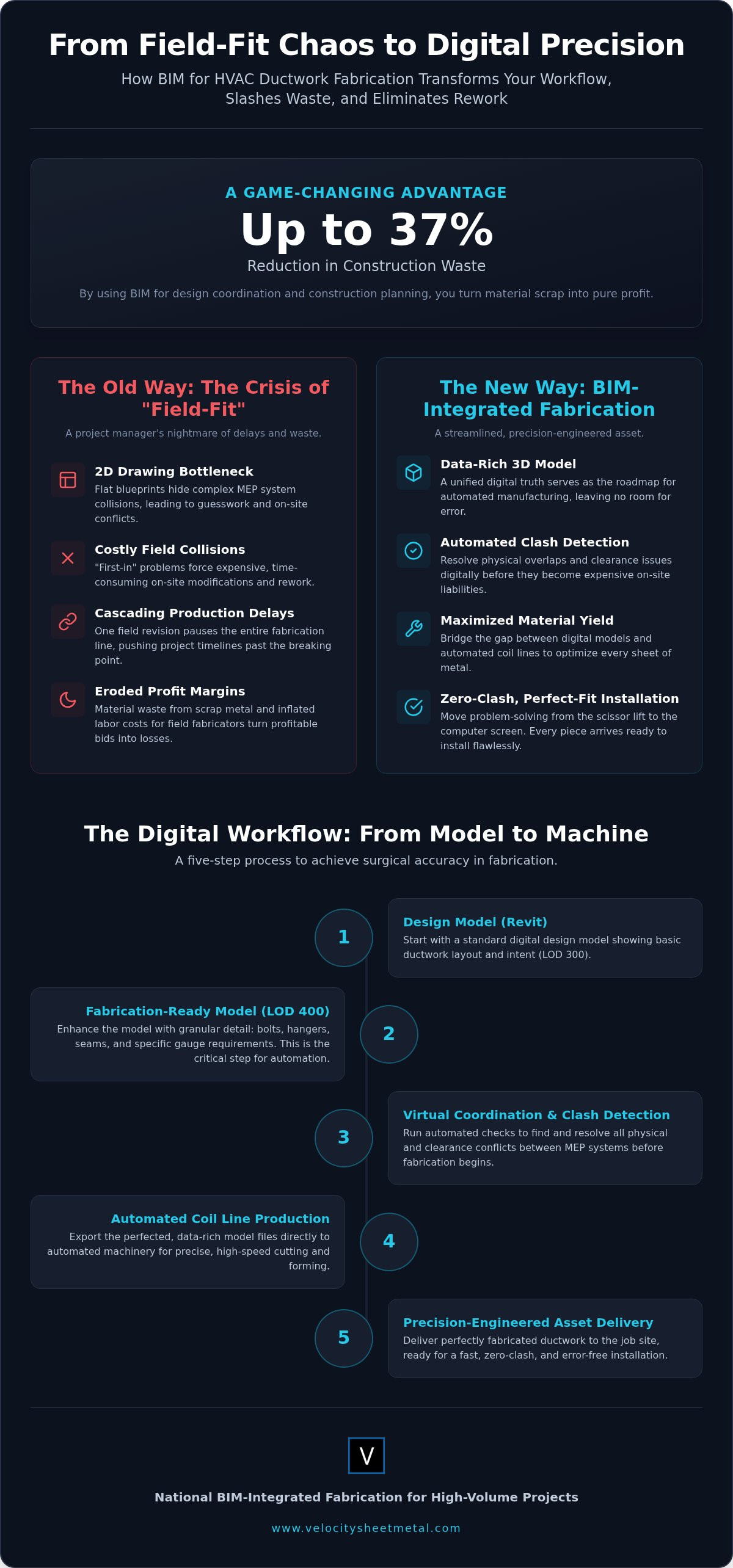
Using BIM for design coordination and construction planning can slash construction waste by up to 37%. In an industry where every scrap of sheet metal and every hour of field labor counts, that's the difference between a profitable job and a total loss. You've likely felt the sting of costly field collisions and the frustration of rework that pushes project timelines past the breaking point. It's a common struggle. You want precision, but traditional methods often deliver delays and waste instead.
This guide explains how BIM for HVAC ductwork fabrication transforms your workflow from a series of field-fitted liabilities into a streamlined, precision-engineered asset. We'll show you how to move from a digital Revit 2026 model to automated fabrication with surgical accuracy. You'll learn the exact steps to achieve a zero-clash installation, maximize your material yield from the coil line, and bridge the gap between the design office and the shop floor. It's time to stop fighting the building and start trusting the model. Let's get to work.
Key Takeaways
- Eliminate the "measure twice, cut once" mindset that leads to field collisions and costly material waste.
- Master the workflow of BIM for HVAC ductwork fabrication to turn digital Revit files into precision-engineered assets ready for the shop floor.
- Use automated clash detection to resolve physical overlaps and clearance issues before they become expensive liabilities during installation.
- Bridge the gap between digital models and automated coil lines to achieve higher material yields and faster project turnaround.
- Scale your operations with BIM-integrated fabrication that ensures standardized quality across high-volume, national accounts.
The Crisis of Field Fit: Why Manual HVAC Ductwork Fabrication is Obsolete
Manual fabrication is no longer a craftsman's pride; it's a project manager's nightmare. In the fast-track construction environment of 2026, the old "measure-twice, cut-once" philosophy has become a costly liability. Relying on field-fitted adjustments creates a cascading series of delays that erode profit margins and inflate labor costs. When your crew spends hours modifying a duct in the air, the entire production line stops. This is the crisis of field fit. It's a relic of an era when buildings were simpler and schedules were longer. Today, that approach is a recipe for failure.
The 2D Drawing Bottleneck
Flat blueprints are fundamentally incapable of managing the density of modern mechanical, electrical, and plumbing (MEP) systems. 2D drawings hide the very collisions that stall installation until it's too late. The "first-in" problem is a constant threat: the first trade on site claims the best path, leaving the HVAC team to navigate a maze of obstructions that weren't visible on the plan. This creates a coordination gap, which is the functional disconnect between the engineer's design intent and the physical reality of the job site. By adopting Building Information Modeling (BIM), contractors move from guesswork to a unified digital truth. Without this foundation, BIM for HVAC ductwork fabrication remains an unreachable goal, leaving teams to fight over inches of ceiling space while the clock ticks.
The Financial Impact of Field Collisions
The cost of a single field-modified fitting is staggering when you factor in specialized labor, material waste, and lost momentum. Every time a fabrication run is paused for a field revision, your project timeline takes a direct hit. Industry data from 2026 suggests that using BIM for design coordination can reduce construction waste by 9% to 37%. That scrap metal represents pure profit being tossed into a bin. Manual shop adjustments are unsustainable as labor rates continue to climb and the pool of skilled field fabricators shrinks. These aren't just minor inconveniences; they are margin-killers that turn a successful bid into a financial loss. Transitioning to a digital-to-physical workflow through BIM for HVAC ductwork fabrication ensures that every piece arriving on site fits perfectly the first time. It moves the problem-solving from the scissor lift to the computer screen, where mistakes are fixed with a click rather than a plasma torch.
Defining BIM for HVAC: The Digital Foundation of Precision Fabrication
Precision starts long before the first sheet of metal hits the coil line. BIM for HVAC is far more than a 3D visualization tool; it's a data-rich digital representation of the physical and functional characteristics of your ductwork. This digital foundation allows contractors to establish rigorous HVAC ductwork fabrication standards that apply across the entire project lifecycle. By moving beyond simple geometry, you're creating a roadmap for automated sheet metal manufacturing that leaves no room for interpretation. The U.S. Army Corps of Engineers Design Manual emphasizes this need for integrated technical data to ensure system performance and reliability in complex builds.
Transitioning from a generic design model to a fabrication-ready digital file is the critical step in modern mechanical construction. Generic models tell you where a duct should go, but they don't tell the shop how to build it. High-speed BIM for HVAC ductwork fabrication requires a shift in mindset. You're no longer just drawing boxes; you're defining the exact parameters that drive automated machinery. This data-driven approach ensures that every fitting, transition, and straight run is optimized for speed and material yield.
Understanding LOD 400 for Fabrication
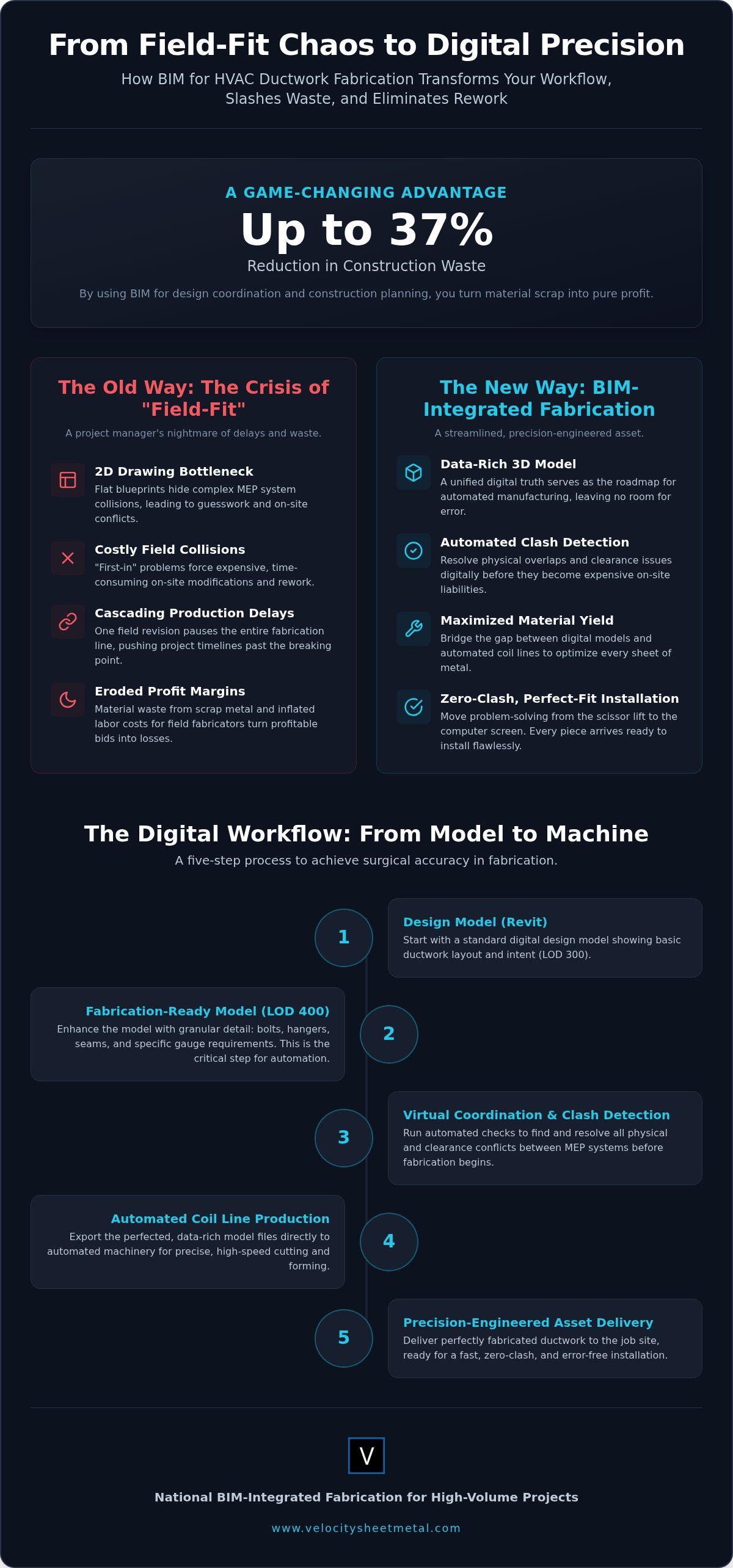
Level of Development (LOD) is the yardstick for digital precision. While LOD 300 is sufficient for design intent, it's a liability for the shop. For successful coil line duct fabrication, you must reach LOD 400. This level includes the granular details that matter on the floor: bolts, hangers, seams, and specific gauge requirements. Without LOD 400, your digital model is just a sketch. With it, your model is a direct instruction set for the plasma cutter. It's the difference between a "close enough" fit and a "perfect every time" installation.
The Role of Mechanical Spooling Services
Mechanical spooling is the bridge between the digital model and the delivery truck. Spool drawings break down complex, continuous duct runs into manageable fabrication units that are easy to build, ship, and install. Each spool is a discrete section of the system, fully detailed and ready for the assembly line. This process ensures that every part is labeled and tracked throughout the workflow. When you leverage Velocity's BIM coordination services, you're ensuring that the transition from the computer screen to the job site is seamless, organized, and fast. Spooling eliminates the chaos of the laydown yard by providing a clear, sequential path for installation.
BIM Clash Detection for HVAC Fabrication: Eliminating Costly Rework
Automated BIM clash detection for HVAC fabrication is the first line of defense against margin erosion. It moves the conflict from the ceiling grid to the cloud, solving geometry problems before the first truck arrives at the job site. You aren't just looking for physical overlaps; you're filtering for operational failure. Hard clashes are the obvious obstacles, such as a supply main running through a structural beam. Soft clashes are the silent killers of a project schedule. These involve required clearances for insulation, maintenance access, or electrical code violations. According to Newcastle University BIM Research, the integration of digital modeling into complex utility networks is essential for managing these overlapping tolerances. Solving these issues digitally reduces field labor by ensuring your crew never arrives to a blocked path.
Multi-Trade MEP Coordination
Successful projects require a unified model. We use Navisworks to compile data from plumbing, electrical, and structural trades into a single, high-fidelity environment. This "virtual build" acts as a high-stakes rehearsal for the physical installation. It allows every trade to see the final product before a single hanger is drilled into the slab. This level of coordination is the backbone of BIM for HVAC ductwork fabrication. It eliminates the finger-pointing that typically occurs when trades collide on site. By the time the duct leaves our shop, the installation sequence is already proven and the path is cleared. This collaborative approach ensures that the most space-intensive trade, HVAC, isn't forced into expensive field workarounds.
Material Optimization and Scrap Reduction
Precision in the model leads directly to efficiency on the shop floor. We use nesting software driven by BIM data to maximize sheet metal yield from every coil. By optimizing duct lengths and fitting shapes within the digital environment, we minimize scrap and utilize standard coil widths more effectively. Research from Gitnux in May 2026 indicates that BIM-based coordination can lead to a 35% reduction in change orders. This lean manufacturing approach doesn't just save money; it's a fundamental part of 2026 sustainable construction practices. Every inch of metal is accounted for in the model, ensuring that your BIM for HVAC ductwork fabrication workflow is as profitable as it is precise. You get more duct on the truck and less waste in the bin.
From Model to Machine: Preparing BIM Files for Automated Coil Line Production
Digital-to-physical workflows are the fastest way to produce ductwork in 2026. Manual data entry on the shop floor is a point of failure you can't afford. By pushing data directly from the model to the machine, you eliminate human error and ensure that what was coordinated is exactly what gets built. This transition is the ultimate payoff of BIM for HVAC ductwork fabrication. It turns a complex design into a set of precise, executable commands for automated machinery. When you remove the need for a shop foreman to manually interpret drawings, you remove the primary source of fabrication delays. Speed and accuracy become the standard, not the exception.
Exporting for Automated Coil Lines
The process starts with converting BIM data into machine-readable formats like .MAJ or .DXF files. These files act as the DNA for the automated coil line. The fabrication software takes the geometry from the Revit model and translates it into specific instructions for cutting, folding, and notching. We maintain tolerances within 1/32nd of an inch from the digital model to the physical metal. This level of precision is impossible with manual layout. It ensures that every segment of rectangular duct fits perfectly with its neighbors, maintaining the integrity of the entire system. Automated lines process these digital specs at a rate that manual shops simply can't match, allowing for high-volume output without sacrificing quality.
Ensuring Dimensional Accuracy in the Model
Accuracy depends on the quality of the digital input. You must verify insulation thicknesses, flange types, and gasket allowances within the digital file before export. If the model specifies 2-inch insulation but the shop builds for 1-inch, the fittings won't work in the field. For heavy-gauge components, accurate wall thickness in the model is critical for CNC press brake bending and final assembly. You also need to ensure that laser cutting design guidelines are met within the model to avoid production bottlenecks. Use this checklist for a successful digital file hand-off to the fabrication shop:
- Service Mapping: Confirm all fittings are mapped to the correct fabrication services within the software.
- Connector Verification: Ensure that flange types (TDC, TDF, S&D) match the project specifications exactly.
- Insulation Offsets: Check that insulation offsets are correctly modeled for either internal or external lining.
- Spool Labeling: Verify that all spools are clearly numbered and tracked for seamless logistics.
If you're ready to move from design to delivery with surgical precision, contact our team for BIM-integrated fabrication services today. We bridge the gap between your digital files and the final physical product, ensuring your project stays on schedule and under budget.
Velocity Sheet Metal: National BIM-Integrated Fabrication for High-Volume Projects
Velocity Sheet Metal operates at the intersection of digital design and industrial production. We provide the standardized quality that national accounts require for large-scale commercial projects. By combining high-speed automated coil lines with expert BIM coordination services, we turn complex Revit models into physical reality with zero field rework. Our 50+ years of combined industry experience ensures that every digital file is reviewed with a fabricator's eye before it ever reaches the shop floor. This is the ultimate execution of BIM for HVAC ductwork fabrication. It’s about more than just software; it’s about a tech-savvy partner who understands the logistics of delivery as well as the physics of sheet metal. We act as a reliable extension of your team, providing a "can-do" attitude grounded in modern manufacturing reality.
National contractors need a partner they can trust to maintain standardized quality across state lines. We position BIM as the essential precursor to high-speed fabrication, cutting through the typical administrative delays that stall traditional shops. Our workflow is fast-paced and methodical. We start with your digital input, move through a rigorous technical review, and end with the precision-engineered product arriving at your site. This controlled, transparent, and repeatable process is why high-volume accounts rely on us for their most demanding mechanical builds. We don't just make duct; we deliver certainty.
National Shipping for Coordinated Projects
Logistics are often the weak link in the construction chain. We've solved this by integrating our shipping process directly with our digital workflow. We package and ship BIM-labeled ductwork to project sites across the US, ensuring that every piece arrives in the correct sequence for installation. This methodical approach allows your crew to pull duct off the truck and move it directly to the hanger. On-time delivery isn't a goal; it's a requirement to match your construction schedule. Whether you're managing a single high-volume build or multiple national project sites, our production remains standardized and predictable. You get the same precision-engineered product every time, regardless of where the job site is located.
Scaling with Precision Laser Cutting
Unique HVAC transition challenges shouldn't stop your production line. We integrate custom laser-cut fittings with our standard rectangular duct runs to maintain project momentum. Engineers and contractors choose our precision laser cutting services because they provide on-demand part production for complex geometry. This capability allows us to handle the "one-off" fittings that typically cause administrative delays in manual shops. By driving our laser cutters with the same BIM for HVAC ductwork fabrication data used for our coil lines, we ensure perfect fitment between standard and custom components. It’s a seamless transition from digital concept to high-volume physical output. We provide the essential bridge between your digital files and a tangible, high-performance product.
Step Into the Future of Precision Fabrication
The industry is moving past manual field fitting toward a digital-to-physical reality. Leveraging BIM for HVAC ductwork fabrication eliminates the coordination gap that stalls projects and erodes margins. You've seen how LOD 400 spooling and automated clash detection turn complex MEP designs into a predictable, sequential assembly process. Mistakes are solved in the model, not on the scissor lift. It’s about creating a streamlined path from the computer screen to the factory floor with surgical precision.
Velocity Sheet Metal acts as your essential bridge from digital file to tangible product. We combine automated coil-line production with precision LOD 400 spooling and national shipping to ensure your high-volume projects stay on track. Our 50+ years of manufacturing expertise ensures every fitting is optimized for speed and accuracy. It’s time to stop fighting the building and start trusting the model. We're ready to help you scale your operations with industrial pragmatism and technical capability.
Request a Quote for BIM-Coordinated HVAC Fabrication and let’s get to work on your next build. Your project deserves the precision of a modern workshop.
Frequently Asked Questions
What is BIM for HVAC ductwork fabrication?
BIM for HVAC ductwork fabrication is the process of using high-fidelity digital models to drive automated manufacturing. It moves beyond simple design intent to include fabrication-level details like specific metal gauges, flange types, and seam locations. This digital DNA ensures that every physical component produced in the shop matches the coordinated model with surgical precision.
How does BIM reduce HVAC installation costs for mechanical contractors?
BIM reduces costs by eliminating field rework and maximizing material yield from the coil line. By identifying and resolving collisions in a virtual environment, you avoid expensive on-site modifications that consume labor and scrap metal. Sourced data indicates that BIM-based coordination can lead to a 35% reduction in change orders, directly protecting your project’s profit margins.
What is the difference between BIM design and BIM fabrication?
BIM design, often at LOD 300, focuses on general routing and spatial requirements within the building. BIM fabrication reaches LOD 400, providing the exact data needed for production, including bolts, hangers, and specific joint connections. Design models show where the duct goes; fabrication models show the shop exactly how to build it for automated machinery.
What software is required for HVAC BIM coordination?
The industry standard in 2026 relies on Autodesk Revit for detailed modeling and Navisworks for comprehensive multi-trade clash detection. Specialized tools like Fabrication CAMduct are then used to translate these digital models into machine-readable files for the shop floor. These programs act as the essential bridge between the engineering office and the automated production line.
How do spool drawings improve on-site assembly speed?
Spool drawings break down complex, continuous duct runs into manageable, pre-labeled units for rapid assembly. Each section is fabricated, tagged, and delivered in the exact sequence required for the construction schedule. This organization eliminates the chaos of the laydown yard and allows installation crews to move directly from the truck to the hangers.
Can BIM help with both rectangular and spiral ductwork?
Yes, BIM coordination is equally effective for rectangular and spiral duct systems. While rectangular duct typically utilizes automated coil lines, spiral and round duct components benefit from digital nesting and precise fitting layouts. The digital model ensures all transitions between different duct shapes are seamless and clash-free before they arrive at the site.
What is clash detection in HVAC BIM?
Clash detection is the automated process of identifying physical overlaps or clearance violations between different trades in the model. We identify "hard" clashes, such as a duct hitting a structural beam, and "soft" clashes, like insufficient space for required insulation or maintenance access. Solving these digitally prevents the work stoppages that occur when trades collide on site.
How do I start the BIM coordination process with a fabrication shop?
Start by providing your design-intent Revit files to our team for a thorough technical review. We elevate your model to LOD 400 and perform multi-trade coordination to ensure a zero-clash installation path. Once the BIM for HVAC ductwork fabrication model is finalized, we push the data directly to our automated machinery for high-velocity production and national delivery.