BIM Clash Detection for HVAC: Eliminating Field Conflicts Before Fabrication
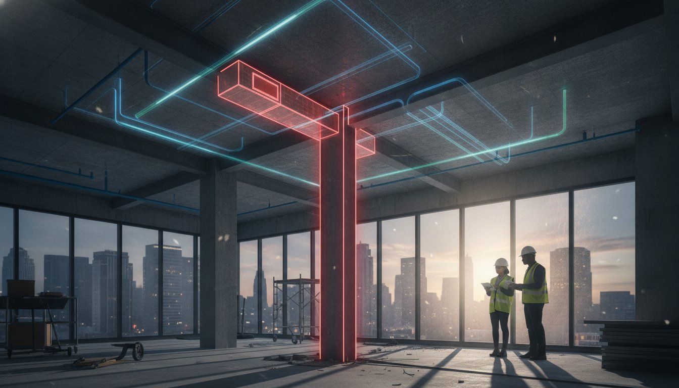
Every minute your crew spends field-modifying a duct is a minute you're losing profit. It's a hard reality in 2026; if it doesn't fit in the model, it won't fit on the floor. Relying on manual coordination leads to material waste, trade friction, and expensive delays. You've likely seen the RFI volume spike the moment the first spool hits the job site. We agree that field rework is the single biggest threat to your project timeline, which is why BIM clash detection for HVAC is no longer an optional luxury for commercial projects.
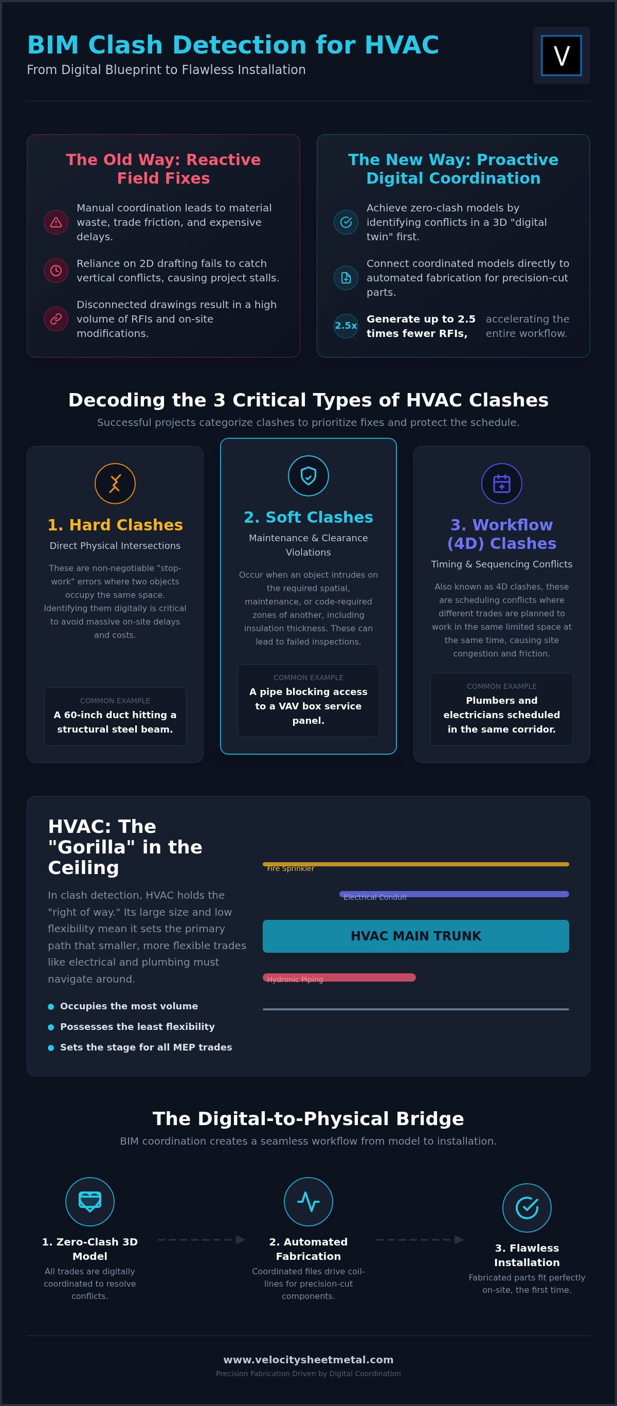
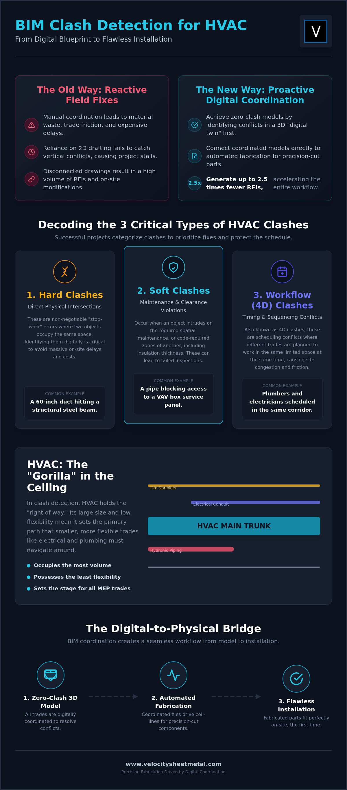
This article explores how digital coordination serves as the essential dry-fit for modern mechanical systems. It moves your project from a complex 3D model to precision automated fabrication without the typical administrative delays that stall production. You'll learn how to achieve zero-clash models that can lead to 2.5 times fewer RFIs and significantly accelerate your fabrication-to-installation workflow. We're breaking down the shift from reactive field fixes to proactive digital coordination. We'll look at how automated coil-line production depends on this digital precision to deliver components that slide into place the first time, every time.
Key Takeaways
- Identify spatial conflicts in 3D before they hit the shop floor. It's the most effective way to stop expensive rework and material waste before it starts.
- Distinguish between hard physical intersections and soft clearance violations. This ensures both structural fit and long-term maintenance access for the entire system.
- Implement BIM clash detection for HVAC to cut RFI volume. It streamlines coordination between trades and keeps the project moving without administrative delays.
- Connect coordinated models directly to automated coil-line production. You'll get precision ductwork that eliminates the need for slow, manual field-measured fittings.
- Leverage spool drawings to bridge the gap between digital files and physical products. It's the key to a faster, more predictable installation timeline.
What is BIM Clash Detection for HVAC Systems?
BIM clash detection for HVAC is the automated process of identifying spatial conflicts within a virtual 3D model before fabrication begins. It serves as a digital "pre-construction" gate. In 2026, this workflow is the standard for any high-density MEP environment. We aren't just looking for ductwork hitting a structural beam. We're looking at the complex intersection of mechanical ducts, hydronic piping, fire protection, and electrical trays. If these components occupy the same physical space in the model, they will fail in the field.
The goal is simple: find the error digitally so you don't find it on the job site. This process moves the project from a series of disconnected drawings to a single, coordinated data environment. It enables a seamless transition from the digital concept to the physical product. By identifying these collisions early, you eliminate the material waste and labor spikes associated with field modifications.
The Shift from 2D Drafting to 3D Coordination
Traditional 2D drafting relied on light-table overlays and manual cross-referencing. This method is obsolete. It consistently fails to catch vertical conflicts, such as a duct running through a sloped gravity pipe or a structural brace. Modern Building Information Modeling (BIM) utilizes software like Revit and Navisworks to create a "digital twin" of the project. This shift allows teams to move from "fixing it in the field" to "solving it in the model." You stop guessing and start verifying. The result is a coordinated model that drives precision fabrication rather than reactive field fixes.
Why HVAC is the Lead Trade in Clash Detection
HVAC is effectively the "gorilla" in the ceiling. Ductwork occupies the most volume and possesses the least flexibility of all MEP trades. Because of this, HVAC typically holds the "right of way" in the coordination hierarchy. Smaller components, like conduit or small-bore piping, are easier to reroute around a main trunk line. BIM clash detection for HVAC ensures the largest components are positioned correctly first. This sets the stage for every other trade. When the ductwork is coordinated, the rest of the mechanical, electrical, and plumbing systems can follow a clear, conflict-free path to installation.
Decoding the 3 Critical Types of HVAC Clashes
Solving conflicts isn't just about clicking a button in Navisworks. You have to understand exactly what you're looking at to prioritize the fix. High-density mechanical rooms are packed with equipment; every inch counts. In 2026, successful projects categorize clashes by their impact on the schedule and budget. This prevents the team from getting bogged down in minor conduit moves while a major duct-to-beam collision remains unresolved. Effective BIM clash detection for HVAC relies on this systematic approach to problem-solving.
Hard Clashes: Duct-to-Structure Interference
A hard clash is a direct physical intersection. Think of a 60-inch rectangular duct trying to occupy the same space as a structural column or a concrete beam. These are non-negotiable errors. Modifying structural steel is a logistical nightmare that involves engineers, added costs, and massive delays. Rerouting the ductwork in a coordinated model is the only logical path. Precision BIM clash detection for HVAC identifies these "stop-work" errors during the design phase. It ensures that when your duct arrives on-site, it actually fits the building's skeleton without needing a plasma cutter and a prayer.
Soft Clashes: Maintenance and Access Zones
Soft clashes involve clearance and maintenance zones. A duct might not hit a pipe, but it might block the access door to a VAV box or prevent a technician from changing a filter. These errors lead to code violations and failed inspections before the building is even occupied. You must also account for insulation thickness in the model. A bare duct might clear a ceiling grid by an inch, but once you add 2-inch wrap, you have a physical conflict. Professionals investigating BIM-based building design coordination emphasize that these clearance issues are often the most common cause of expensive field rework.
Workflow clashes, or 4D clashes, are about timing and sequencing. If the mechanical contractor and the plumber are scheduled to work in the same tight corridor on the same day, you have a conflict. These scheduling overlaps cause trade friction and site congestion. By identifying these during the coordination phase, you can adjust the master schedule to keep the site moving efficiently.
Categorizing these issues allows you to prioritize the "big wins" first. Once the hard and soft clashes are resolved, you can move to fabrication with total confidence. Our BIM coordination and spool drawings provide the exact roadmap needed to turn these digital resolutions into physical reality without the guesswork.
The Digital-to-Physical Bridge: How BIM Powers Automated Fabrication
BIM is more than a 3D visualization tool; it's the digital DNA of your project. When you finalize BIM clash detection for HVAC, you aren't just clearing virtual space. You're generating a precise manufacturing roadmap. This digital-to-physical bridge is what separates high-performance contractors from those stuck in the past. It eliminates the "field-measured" fitting, a relic of an era when coordination happened on a notepad. Today, the model drives the machine with surgical precision.
The accuracy of your fabrication is directly tied to the quality of your coordination. If the model is clash-free, the data sent to the shop is gold. This BIM-to-Machine workflow ensures that every component arriving at the job site is ready for immediate installation. You stop wasting time on field modifications and start focusing on project delivery. This transition from a digital file to a tangible product is the essential step for modern, high-speed construction.
Automated Rectangular Duct Production
Coordinated models feed data directly into an automated coil-line. This workflow maximizes speed and ensures every straight section of duct matches the model's exact dimensions. By standardizing duct lengths based on the coordinated layout, you reduce the number of joints and potential leak points. This level of precision is only possible when the model is verified through BIM clash detection for HVAC. It also allows for material optimization. The software nests parts to reduce scrap metal, turning digital efficiency into physical savings. This integration is the core of coil line duct fabrication, where high-volume production meets high-accuracy design.
Custom Laser Cutting for Complex Fittings
The most difficult parts of any HVAC system are the transitions, offsets, and elbows. These are the areas where clashes are most likely to occur. Precision laser cutting turns these complex digital geometries into perfectly fitting components. When you use coordinated models, you can fabricate every unique fitting in the shop rather than guessing in the field. Precision laser cutting ensures that an offset designed to clear a plumbing line by half an inch does exactly that. There's no "cut to fit" on the job site. You model once and fabricate once. This mantra streamlines the entire installation process, moving you from delivery to hanging duct in record time.
A Systematic Workflow for HVAC Coordination
Successful coordination follows a logical, repeatable sequence. It mirrors a production line where every input must be verified before the next stage begins. In 2026, the industry has moved beyond haphazard emails. We now use a federated model environment where every trade's data lives in one place. This transparency ensures that BIM clash detection for HVAC isn't just a software check, it's a project management strategy. The process moves from digital aggregation to physical sign-off with surgical precision.
The workflow typically follows five essential steps:
- Step 1: Model Aggregation. We bring structural steel, plumbing, fire protection, and electrical models into a single environment.
- Step 2: Automated Reporting. We run clash reports using software like Navisworks to identify every hard and soft conflict.
- Step 3: Conflict Resolution. Teams meet to assign responsibility. The "right of way" rules determine who moves and who stays.
- Step 4: Verification. The HVAC model is updated. We re-run clash detection to ensure the fix didn't create a new problem elsewhere.
- Step 5: Final Sign-off. Once the model is "clash-free," it is locked for fabrication.
The Role of Mechanical Spooling
A coordinated model is only useful if the field crew can install it. Mechanical spooling breaks the massive 3D model into bite-sized, manageable sections for the shop. These "spools" include all the data needed for our automated coil-line. We use mechanical spooling services to tag every piece of duct with a unique ID. This enables "Lego-style" assembly on the job site. Your crew doesn't need to guess where a fitting goes; they just follow the spool map. This eliminates field measurements and keeps the installation pace fast and predictable.
Managing Revision Control
The biggest risk in fabrication is building from an outdated file. Coordination is iterative. Models change daily. We maintain strict revision control to ensure the shop always builds from the latest "Coordinated" set. This prevents the costly mistake of fabricating duct for a design that was changed two weeks ago. By tracking every modification, we bridge the gap between the design office and the factory floor. This discipline ensures that what we ship matches the final, approved model exactly. To start your next project with this level of precision, explore our BIM coordination and spool drawings today.
Precision Fabrication: The Logical Conclusion of BIM Coordination
A coordinated model is only as valuable as the shop that builds it. You can spend weeks perfecting a 3D environment, but if the fabrication shop relies on manual measurements, the effort is wasted. BIM clash detection for HVAC reaches its full potential when it's integrated directly with automated machinery. We bridge the gap between the digital file and the physical product. Our integrated BIM-to-Machine workflows ensure that every data point from the coordinated model translates into a precise physical component. It's a seamless transition from the screen to the shop floor.
This approach significantly reduces the total cost of ownership for your project. You save on labor by eliminating field rework. You save on materials by reducing scrap through digital nesting on our automated coil-line. Most importantly, you save time. By moving from the virtual 3D space directly to production, you move your project closer to completion with every spool we ship. It's a methodical progression from data to delivery that keeps your timeline intact.
Standardizing Quality for National Accounts
Consistency is the primary challenge for national accounts managing multiple project sites across the country. We provide a standardized quality level that doesn't vary by region. Whether your project is in a major metro or a remote site, our national shipping ensures you receive the same precision-coordinated ductwork everywhere. We leverage 50 plus years of expertise to solve complex HVAC challenges before they reach the job site. This national focus allows us to support large-scale rollouts with a "can-do" attitude grounded in modern manufacturing reality. From the initial digital concept to the final physical result, we maintain a tight grip on quality control.
Ready to Coordinate Your Next Project?
Transitioning from complex digital files to high-volume rectangular duct shouldn't be a source of friction. It should be a source of speed. Partnering with a BIM-integrated fabrication shop means you're hiring a tech-savvy partner obsessed with detail. We cut through the typical administrative delays of the industry. We act as the essential bridge between your coordinated model and a tangible, high-quality product. Don't let your coordination efforts stop at the computer screen. Take the logical next step and ensure your fabrication matches your model's precision. Request a quote for BIM-coordinated HVAC fabrication and see how our automated workflow accelerates your timeline.
Accelerate Your Fabrication-to-Installation Timeline
Precision is the only way to protect your profit margins in 2026. Successful mechanical projects depend on resolving conflicts before they reach the shop floor. By implementing BIM clash detection for HVAC, you move from reactive field fixes to proactive digital coordination. This ensures that every spool arriving at your job site fits the first time. It eliminates the administrative delays of RFIs and the material waste of incorrectly fabricated fittings. You stop guessing and start verifying.
At Velocity Sheet Metal, we turn your coordinated models into physical components with surgical accuracy. We leverage an automated coil-line and precision laser cutting to deliver ductwork that matches your digital DNA exactly. With 50 plus years of combined industry experience, we provide standardized quality and national shipping for your most complex projects. We act as the essential bridge between your design file and a tangible product. Partner with Velocity for Precision BIM-Integrated Fabrication and keep your project moving forward with total confidence.
Frequently Asked Questions
What software is most commonly used for HVAC clash detection?
Autodesk Navisworks Manage and Revit are the primary tools for mechanical coordination. As of 2026, Solibri version 26.6.1 is also a major player for AI-powered model validation and advanced point cloud checking. These platforms allow contractors to federate models from multiple trades into a single environment. This transparency is vital for identifying collisions early. Using these tools ensures that your digital "dry-fit" is accurate before a single piece of metal is cut.
How much does BIM coordination typically save on a commercial project?
Savings are realized through efficiency and risk mitigation rather than just lower material costs. BIM-enabled workflows have been shown to reduce construction project delivery time by 46 percent. Additionally, projects adopting 4D and 5D BIM report up to 30 percent improvements in schedule reliability. By avoiding field rework and trade friction, you protect your profit margins. You spend less on labor and eliminate the material waste caused by incorrectly fabricated fittings.
What is the difference between a hard clash and a soft clash in HVAC?
A hard clash occurs when two components physically intersect, such as a large rectangular duct running through a structural column. A soft clash, or clearance clash, happens when an element violates required space for maintenance, safety, or insulation. For example, a duct might block access to a VAV box filter. Both types of conflicts are identified during BIM clash detection for HVAC to ensure the system is both buildable and maintainable.
Can BIM clash detection be used for existing building renovations?
Absolutely. For renovations, we use 3D laser scanning to capture the "as-built" conditions of the existing structure. This point cloud data is integrated into the model to identify conflicts between new ductwork and existing utilities. It's a critical step for modernizing older facilities where ceiling space is often extremely limited. This process prevents the common problem of discovering a hidden structural brace only after the new duct arrives on a project site.
Who is responsible for resolving clashes in a multi-trade project?
Resolution is a collaborative effort led by the BIM Manager or General Contractor. During coordination meetings, clashes are reviewed and assigned to specific trades for revision. The "right of way" principle usually guides these decisions. Since large-scale ductwork is the least flexible component, other trades like electrical or plumbing often reroute their smaller lines around the HVAC path. This systematic approach ensures a clear, conflict-free installation for every trade involved.
How does clash detection impact HVAC ductwork fabrication timelines?
It streamlines the process by providing verified data for immediate production. Instead of waiting for field measurements, the shop starts fabrication as soon as the coordinated model is signed off. This integration with BIM clash detection for HVAC allows us to feed data directly into an automated coil-line. You move from digital design to physical product much faster. This reduces the overall lead time for complex commercial duct systems across the country.
What are spool drawings and why are they necessary after clash detection?
Spool drawings are the fabrication maps generated from a coordinated 3D model. They break the system down into specific, tagged segments that are ready for the shop floor. These drawings are essential because they bridge the gap between a complex model and the physical installation. They provide the shop with exact dimensions for automated cutting and give the field crew a clear roadmap for fast, predictable assembly on the job site.
Does BIM coordination reduce the need for on-site HVAC installation adjustments?
It nearly eliminates the need for field modifications. When you coordinate the model properly, the ductwork is fabricated to fit the exact spatial constraints of the building. This leads to 2.5 times fewer Requests for Information (RFIs) during construction. Your crew doesn't have to "make it fit" on-site. Instead, they follow the spool drawings for a seamless installation. This requires no cutting, no welding, and no expensive field rework.